Audi Q5: Door, Removing and Installing
Removing
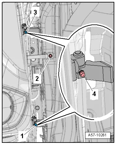
- Disconnect the connector on the A-pillar. Refer to → Electrical Equipment; Rep. Gr.97; Connectors.
- Remove the door arrester bolt -2-.
- Remove the cover caps -1- and -3- from the stud bolts.
- Remove the stud bolts -4- on the upper and lower door hinge.
 Caution
Protect the painted surfaces on the door or on the side panel from damage.
- Carefully remove the door upward out of the door hinges.
Installing
 Note
Note
Do not make any adjustments after installing the door.
Door, Adjusting
Special tools and workshop equipment required
- Gauge - Gap Adjustment -3371-
- Door Template - T40038 /9-
- The "min and max" markings are used to check the lateral adjustment.
- The groove in the center of the template is used to check the height.
- The 0.4 mm graduation is used for checking the recess of the front door to the fender, or of the rear door to the front door.
- The 0.6 mm graduation is used to check the recess of the trim on the "B-pillar" from the rear door to the front door.
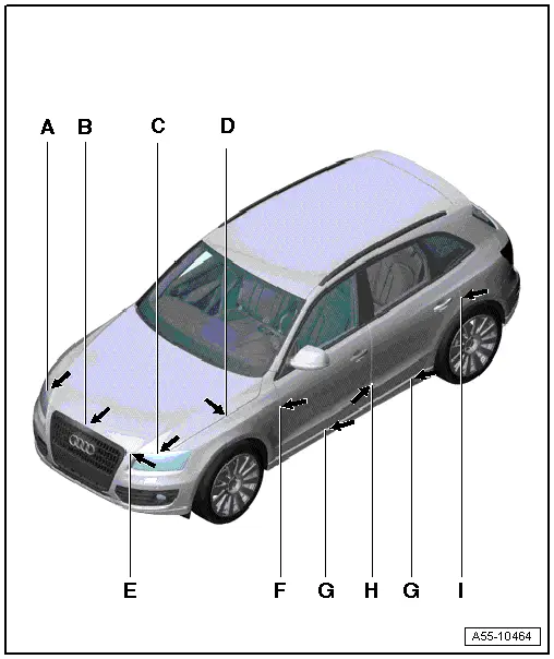
Gap Dimensions
 Note
Note
- All dimensions are in "mm".
- All dimension tolerances are +-0.5 mm.
- The parallel alignment of the gap must not exceed 0.5 mm.
- Dimension -F- = 3.5 mm
- Dimension -H- = 4.5 mm
- Dimension -I- = 3.5 mm
Driver Side:
- Remove the driver side instrument panel cover. Refer to → Body Interior; Rep. Gr.68; Storage Compartments and Covers; Driver Side Instrument Panel Cover, Removing and Installing.
- Remove the lower B-pillar trim. Refer to → Body Interior; Rep. Gr.70; Passenger Compartment Trim; A-Pillar Trim Panel, Removing and Installing.
- Remove the driver side relay carrier mount. Refer to → Electrical Equipment; Rep. Gr.97; Relay Panels, Fuse Panels and E-Boxes.
Front Passenger Side:
- Remove the glove compartment. Refer to → Body Interior; Rep. Gr.68; Storage Compartments and Covers; Glove Compartment, Removing and Installing.
Continued for both Sides:
- Remove the A-pillar connector station. Refer to → Electrical Equipment; Rep. Gr.97; Connectors.
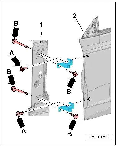
Adjustment in Longitudinal Direction
- Loosen the bolts -B arrows- on the top and bottom of the hinge and on the A-pillar -1-.
- Adjust the door -2- lengthwise.
- Tighten the bolts -B arrows-.
- Tightening specification. Refer to -item 7-.
Height Adjustment
 Note
Note
- The hinge screws on the door, refer to -item 8- are so-called fitting screws, therefore it is not necessary to adjust the door using these screws.
- If it is necessary to make an adjustment using these bolts, the bolt can be replaced with one of the same length and strength category.
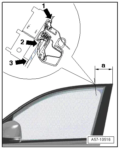
- Use the Door Template - T40038 /9- to adjust.
- Place the template in distance -a- = 150 mm.
- When correctly adjusted, the template must contact the roof and trim strip "point 1" (-arrows-) as illustrated.
- At "point 2" the bottom of the window guide must be inside the groove.

Adjustment to Center of Vehicle
- Use the Door Template - T40038 /9- to adjust.
- Place the template in distance -a- = 150 mm.
- Loosen the bolts -A arrows-, on the top and bottom of the hinge.
- Adjust the door -2- lengthwise.
- Tighten the bolts -A arrows-.
- For the "min" position, "points -1- and -3-" must touch.
- "Point -2-" may show a gap.
- For the "max" position, "points -2- and -3-" must touch.
- "Point -1-" may show a gap.
- Tightening specification. Refer to -item 8-.
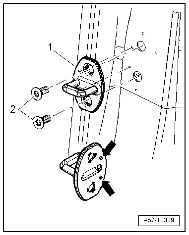
Striker Pin, Adjusting
 Note
Note
- When adjusting the striker pin, move it only toward the center of the vehicle.
- Do not adjust the door height using the striker pin because the door lock will be damaged.
- Loosen the bolts -2-.
- Slide the striker pin -1- until the door is flush with the body contours.
- Striker pin must align in door lock center for correct adjustment.
- Tighten the bolts -2-.