Audi Q5: Overview - Brake Pedal
 Note
Note
Grease all bearings and contact surfaces with Polycarbamide Grease -G 052 142 A2-
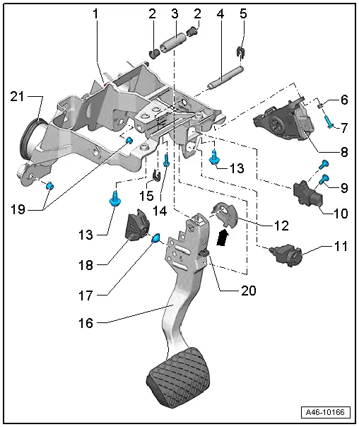
1 - Mounting Bracket for Pedal Assembly
- Illustration for vehicles with automatic transmission
2 - Sleeve
3 - Brake Pedal Axle
4 - Mounting Pin
5 - Right Securing Clip (Spring Steel)
- Refer to Parts Catalog.
6 - Washer
7 - Gas Pedal Module Bolt
- Tightening specification. Refer to → Rep. Gr.20; Accelerator Pedal Mechanism; Overview - Accelerator Pedal Mechanism
8 - Accelerator Pedal Module
9 - Bolt
- 8 Nm
10 - Brake Pedal Position Sensor -G100-
Only for hybrid vehicles
- Refer to → Chapter "Brake Pedal Position Sensor -G100-, Removing and Installing"
11 - Brake Lamp Switch -F-
- Refer to → Chapter "Brake Lamp Switch, Removing and Installing"
12 - Magnet Carrier
Only for hybrid vehicles
- For the brake pedal position sensor
- The centering pin -arrow- must audibly engage when installing at the brake pedal
13 - Pedal Support Bolt
- 20 Nm
14 - Mounting Pin Bolt
- 8 Nm
- The bolt holds the mounting pins in position
15 - Left Securing Clip (Spring Steel)
- Refer to Parts Catalog.
16 - Brake Pedal
 WARNING
The path of the brake pedal must not be shortened via extra floor mats.
17 - Ball Socket Formed in Mount
- For the ball head on the brake booster push rod
18 - Mount
- For the ball head on the brake booster push rod
- With ball stud retaining tabs
19 - Nut
- 8 Nm
20 - Stop
 Note
Note
If possible, leave the brake pedal stop installed; it could break the mount for the brake lamp switch if the brake pedal is released too quickly.
21 - Grommet
- Only installed on vehicles with automatic transmission

