Audi Q5: Pressures, Checking
- Observe the test requirements. Refer to → Chapter "Test Requirements".
- Turn off the ignition.
- Connect the A/C service station. Refer to → Chapter "A/C Service Station, Connecting".
Vehicles with an electric operated valves in the refrigerant circuit, which cannot be opened without power (for example the Audi Q7 e-tron):
 Note
Note
On vehicles with high-voltage system and additional functions of the A/C system ("heat pump operation" or "cooling the high-voltage battery") valves may be installed in the refrigerant circuit which cannot be opened without power. These valves are opened and closed for example via a step motor and after switching off the ignition are no longer activated. To check the pressures in the refrigerant circuit with the A/C system switched off no areas may be closed be closed, for this reason the valves must be opened before these procedures. Refer to → Heating, Ventilation and Air Conditioning; Rep. Gr.87; Refrigerant Circuit; System Overview - Refrigerant Circuit and the Vehicle Diagnostic Tester in the "Guided Fault Finding" function.
- Open the electrically activated valves, which to now open without power using the Vehicle Diagnostic Tester in the "Guided Fault Finding" function.
All Vehicles
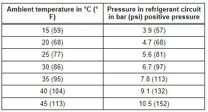
- Take the pressure gauge readings (two possible results):
- Pressure in refrigerant circuit lower than indicated in table
- Pressure in refrigerant circuit in line with table or higher
 Note
Note
- Temperature of refrigerant circuit components should be equal to ambient temperature. Pressure will deviate from values in table if individual components of refrigerant circuit are warmer or colder.
- At absolute pressure, 0 bar/psi corresponds to absolute vacuum. Normal ambient pressure (positive pressure) corresponds to 1 bar (14.5 psi) absolute pressure. 0 pressure corresponds to an absolute pressure of 1 bar (14.5 psi) on most pressure gauges (indicated by -1 bar (-14.5 psi) below 0).
- For vehicles with High Pressure Sensor -G65-, Refrigerant Circuit Pressure Sensor -G805- or A/C Pressure/Temperature Sensor -G395-, etc. for which measured pressure is displayed in measured value block, pressure measured should coincide. Use the Vehicle Diagnostic Tester ("OBD" or "Guided Fault Finding for the A/C system") and → Heating, Ventilation and Air Conditioning; Rep. Gr.87; System Overview - Refrigerant Circuit (vehicle-specific repair manual).
- Pressure is measured in different units: 1 MPa (145 psi) corresponds to 10 bar (145 psi) positive pressure. 1 bar (14.5 psi) absolute pressure corresponds to 0 bar/psi positive pressure and thus to the ambient pressure (atmospheric pressure).
Pressure in refrigerant circuit lower than indicated in table
Not enough refrigerant in refrigerant circuit
- Determine refrigerant circuit leaks. Refer to → Chapter "Refrigerant Circuit, Determining Leaks ".
- Check the pressure relief valve.
If pressure relief valve has responded:
- Check the coolant fan activation.
- Check the refrigerant lines and hoses for cross-section constrictions caused by inadequate bending radii.
- Check the refrigerant lines and hoses for external damage.
- If no fault is found, clean the refrigerant circuit (flush using refrigerant R134a. Refer to → Chapter "Refrigerant Circuit, Cleaning (Flushing), with Refrigerant R134a"; or blow through using compressed air and nitrogen. Refer to → Chapter "Refrigerant Circuit, Flushing with Compressed Air and Nitrogen").
Pressure in refrigerant circuit in line with table or higher
- Start the engine or activate the ready mode (for example on vehicles with a high-voltage system).
- Set the A/C system to maximum cooling output.
 Note
Note
- On vehicles with A/C Compressor Regulator Valve -N280-, the control current can be read in the measured value block. Use the Vehicle Diagnostic Tester (Function "OBD" or "Guided Fault Finding" of the Air Conditioning) and → Heating, Ventilation and Air Conditioning; Rep. Gr.87; A/C Compressor (vehicle-specific repair manual).
- On vehicles with an Electrical A/C Compressor -V470- read out the A/C Compressor Speed Sensor using the different control modules (for example via the respective climate control module or the Thermal Management Control Module -J1024-) using the Vehicle Diagnostic Tester in the "Guided Fault Finding" function.
Vehicles with a Mechanically Driven A/C Compressor
If A/C compressor is not driven with the engine running or regulating valve is not actuated:
- Determine and eliminate cause, for example by checking A/C system DTC memory.
- Observe the test conditions.
- Check the A/C Clutch -N25- voltage supply. If it is OK, repair the A/C clutch.
- Check the A/C Compressor Regulator Valve -87- activation. Use the Vehicle Diagnostic Tester (Function "OBD" or "Guided Fault Finding" of the Air Conditioning) and → Heating, Ventilation and Air Conditioning; Rep. Gr.87; A/C Compressor (vehicle-specific repair manual).
 Note
Note
- If the low pressure switch was removed to connect the service station, bridge the electrical connections in the corresponding connector for the pressure measurement.
- A/C compressor is driven by the engine via A/C Clutch -N25-.
- The A/C Compressor Regulator Valve -N280- is activated by the Front A/C Display Control Head -E87- or Climatronic Control Module -J255-. Use the Vehicle Diagnostic Tester (Function "OBD" or "Guided Fault Finding" of the Air Conditioning) and → Heating, Ventilation and Air Conditioning; Rep. Gr.87; System Overview - Refrigerant Circuit (vehicle-specific repair manual).
Vehicles with an Electrical A/C Compressor -V470- (Vehicles with a High-Voltage System)
If the electrical A/C Compressor is not activated while the ready mode is active:
- Check the activation of the A/C compressor via the respective control module. Refer to → Heating, Ventilation and Air Conditioning; Rep. Gr.87; Refrigerant Circuit; System Overview - Refrigerant Circuit and use the Vehicle Diagnostic Tester in the "Guided Fault Finding" function.
All Vehicles
- Checking pressures on vehicles with a restrictor and reservoir (with internally regulated A/C compressor). Refer to → Chapter "Checking Pressures for Vehicles with Restrictor and Reservoir (with Internally Regulated Compressor)".
- Checking pressures on vehicles with an expansion valve and receiver/dryer (with internally regulated A/C compressor). Refer to → Chapter "Checking Pressures on Vehicles with Expansion Valve and Receiver/Dryer (with Internally Regulated Compressor)".
- Checking pressures for vehicles with restrictor, reservoir and A/C Compressor Regulator Valve -N280- (externally regulated A/C compressor). Refer to → Chapter "Vehicles with Restrictor, Reservoir and A/C Compressor Regulator Valve -N280- (Externally Regulated A/C Compressor), Checking Pressures".
- Checking pressures on vehicles with restrictor, receiver/dryer and A/C Compressor Regulator Valve -N280- (externally regulated compressor). Refer to → Chapter "Vehicles with Restrictor, Receiver/Dryer and A/C Compressor Regulator Valve -N280-, Checking Pressures, Externally Regulated Compressor".
- Check the pressures on vehicles with an electrically-driven A/C compressor (Audi A3 e-tron, Audi Q5 hybrid, Audi Q7 e-tron etc.). Refer to → Chapter "Checking Pressures on Vehicles with Electrically Driven A/C Compressor (Vehicles with Hybrid Drive)".

