Audi Q5: Cell Phone Preparation Preliminary Setup Connector Assignment
 Note
Note
Unlisted connector terminals are not assigned.
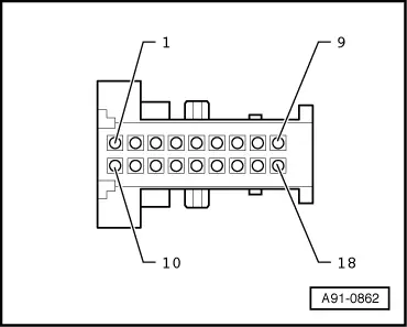
Black 18-pin connector (T18a)
1 - Terminal 31
4 - LF mute wire to Radio -R-/Information Electronics Control Module 1 -J794-
7 - LF (-) to Radio -R-
9 - Microphone IN (-) for the Microphone Unit in Front Roof Module -R164- (Left Front Microphone -R140-)
10 - Terminal 15
11 - Terminal 30
16 - LF (+) to Radio -R-
18 - Microphone IN (+) for the Microphone Unit in Front Roof Module -R164- (Left Front Microphone -R140-)
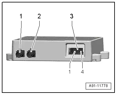
Cellular Telephone Amplifier -R86- Connector Assignment, through MY 2012
Cellular Telephone Amplifier -R86-
1 - GSM Antenna Connection (Purple) from Roof Antenna -R216-
2 - Antenna Connection (Purple) to Telephone Baseplate -R126-
3 - Black 4-pin multipin connector (T4ak)
 Note
Note
Unlisted connector terminals are not assigned.
3 - Black 4-pin multipin connector (T4ak)
1 - Terminal 30
2 - Terminal 31
3 - Switch-on signal for the Telephone Transceiver -R36- (CAN)/Information Electronics Control Module 1 -J794- (MMI)
4 - Control pin (not used)

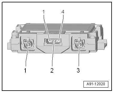
Cell Phone Amplifier -R86- Connector Assignment, from MY 2013
Cellular Telephone Amplifier -R86-
1 - Antenna Connection (GSM) from the Roof Antenna -R216-
2 - Black 4-pin multipin connector (T4ak)
3 - Antenna connection to the Telephone Baseplate -R126-
 Note
Note
Unlisted connector terminals are not assigned.
2 - Black 4-pin multipin connector (T4ak)
1 - Terminal 30
2 - Terminal 31
3 - Switch-on signal for the Telephone Transceiver -R36- (CAN)/Information Electronics Control Module 1 -J794- (MMI)
4 - Control pin (not used)

Cell Phone Preparation Connector Assignment, CAN
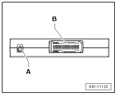
Telephone Transceiver -R36-
A - Bluetooth Antenna -R152- connection, yellow
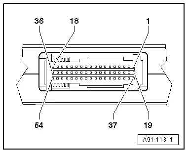
B - 54-pin connector (T54a)
 Note
Note
Unlisted connector terminals are not assigned.
B - 54-pin connector (T54a)
1 - Terminal 30
2 - Terminal 31
8 - LF (+) to Radio -R-
9 - LF (-) to Radio -R-
10 - Terminal 31 ground shielding (not used)
11 - Microphone IN (+) for the Microphone Unit in Front Roof Module -R164- (Left Front Microphone -R140-)
12 - Microphone IN (-) for the Microphone Unit in Front Roof Module -R164- (Left Front Microphone -R140-)
16 - NF mute, not used
17 - CAN Bus high (Infotainment)
18 - CAN Bus low (Infotainment)
Cell Phone Preparation Connector Assignment, MMI
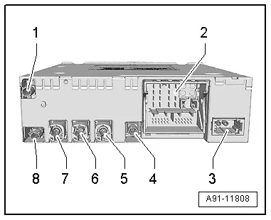
Information Electronics Control Module 1 -J794-
1 - Not Assigned
2 - Connection block with four multipin connectors
3 - MOST Bus
4 - Not Assigned
5 - 4-pin connector (T4am) for the Front Information Display Control Head -J685-
6 - 4-pin connector (T4ap) to External Audio Source Connection -R199-
7 - Not Assigned
8 - Not Assigned
 Note
Note
Unlisted connector terminals are not assigned.
2 - Connection block with four multipin connectors
A - Brown 8-pin connector (T8ah)
1 - Not Assigned
2 - Power Supply to Multimedia System Control Head -E380-
3 - Wake UP to Multimedia System Control Head -E380-
4 - Not Assigned
5 - Switch-on signal to Telephone Baseplate -R126-
6 - Reset to the Multimedia System Control Head -E380-
7 - Ring-break Diagnostic Cable
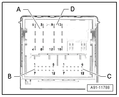
B - Blue 12-pin connector (T12x)
8 - Microphone IN (+) for the Microphone Unit in Front Roof Module -R164- (Left Front Microphone -R140-)
9 - Microphone IN (-) for the Microphone Unit in Front Roof Module -R164- (Left Front Microphone -R140-)

C - Green 12-pin connector (T12y)
All pins are connected to the External Audio Source Connection -R199-.
1 - LF-In ground
2 - Right LF-In
3 - USB (+5V)
4 - USB (ground)
5 - Not Assigned
6 - Detect
7 - Left LF-In
8 - LF-In ground shielding
9 - CVBS cable (+)
10 - CVBS cable (-)
11 - iPod data
12 - iPod data

D - Black 8-pin connector (T16q)
10 - Data from Multimedia System Control Head -E380-
11 - Data to the Multimedia System Control Head -E380-
12 - Terminal 31
14 - Reset from Multimedia System Control Head -E380-
15 - Terminal 30
16 - Ground to Multimedia System Control Head -E380-

3 - MOST Bus
1 - Input
2 - Output