Audi Q5: Central Locking
Component Location Overview - Central Locking
 Note
Note
- Central locking functions electronically.
- The adjusters in the doors are integrated inside the door lock and have 2 motors.
- The adjusters cannot be replaced separately.
- The first motor locks the door and the second motor locks the interior door mechanism (Safe function).
- The door can no longer be opened from the inside.
- The central locking control module will unlock any locked doors if there is a crash and the airbag deploys.
- The central locking control module is located inside the right rear side panel.
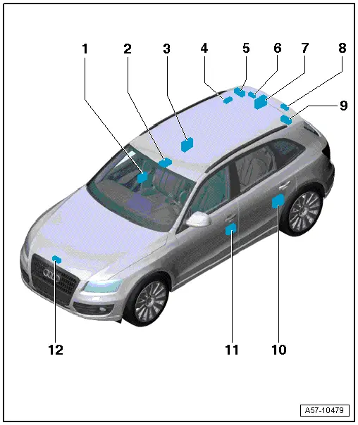
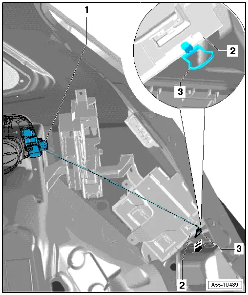
1 - Front Passenger Door Control Module -J387-
- Removing and installing. Refer to → Chapter "Driver Door Control Module -J386- and Front Passenger Door Control Module -J387-, Removing and Installing".
2 - Anti-Theft Alarm System Sensor -G578-
3 - Right Rear Door Control Module -J389-
- Removing and installing. Refer to → Chapter "Left Rear Door Control Module -J388- and Right Rear Door Control Module -J389-, Removing and Installing".
4 - Fuel Filler Door Unlock Motor -V155-
- Removing and installing. Refer to → Chapter "Fuel Filler Door Unlock Motor -V155-, Removing and Installing".
5 - Rear Lid Control Module 2 - J756-
6 - Vehicle Positioning System Interface Control Module -J843-
- Removing and Installing. Refer to → Chapter "Vehicle Positioning System Interface Control Module -J843-, Removing and Installing".
7 - Comfort System Central Control Module -J393-
- Removing and installing. Refer to → Chapter "Comfort System Central Control Module -J393-, Removing and Installing".
8 - Rear Lid Unlock Motor - V139-
- Removing and installing. Refer to → Fig. " Rear Lid Unlock Motor - V139- ".
9 - Rear Lid Control Module -J605-
- Removing and installing. Refer to → Chapter "Overview - Rear Lid Motor".
10 - Left Rear Door Control Module -J388-
- Removing and installing. Refer to → Chapter "Left Rear Door Control Module -J388- and Right Rear Door Control Module -J389-, Removing and Installing".
11 - Driver Door Control Module -J386-
- Removing and installing. Refer to → Chapter "Driver Door Control Module -J386- and Front Passenger Door Control Module -J387-, Removing and Installing".
12 - Engine Hood Contact Switch -F266-
Driver Door Control Module -J386- and Front Passenger Door Control Module -J387-, Removing and Installing
- Remove the door trim panel. Refer to → Body Interior; Rep. Gr.70; Front Door Trim Panels; Front Door Trim Panel, Removing and Installing.
- Open the release and the disconnect the connectors -1- and -2-.
- Disconnect the connector -3-.
- Disconnect the connector -4- on the door control module.
- Press the retaining detent -5- in direction of -arrow- and disengage the door control module -6- on the door shell.
Installing
- Installation in reverse order of removal making sure the retainer locks into the inner door panel.
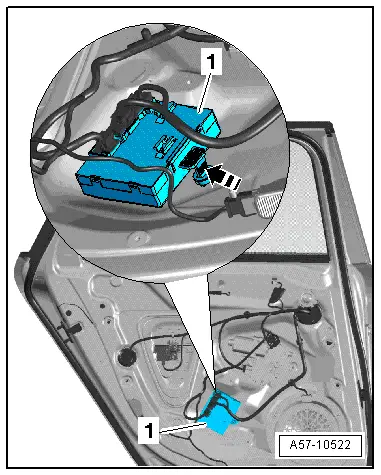
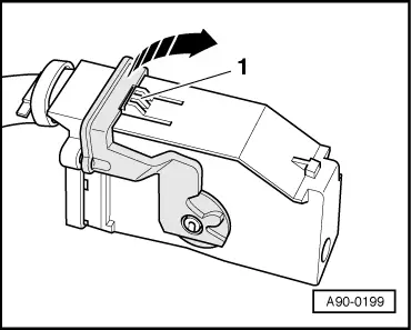
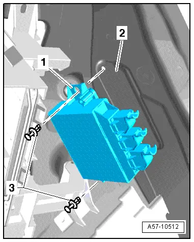
Left Rear Door Control Module -J388- and Right Rear Door Control Module -J389-, Removing and Installing
- Push the release downward and disconnect the connectors.
- Press the catch in direction of -arrow- and disengage the door control module -1- from the door shell.
Installing
- Installation in reverse order of removal making sure the retainer locks into the inner door panel.
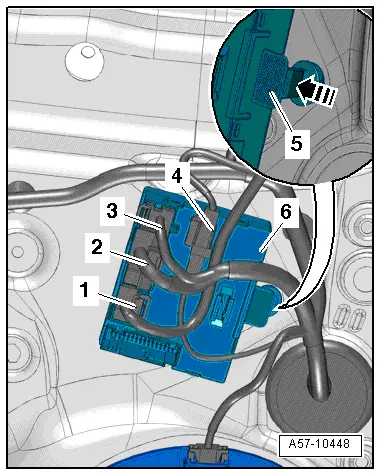
Comfort System Central Control Module -J393-, Removing and Installing
- Open the right luggage compartment side trim panel.
- Open the clips -arrows- and remove the Comfort System Central Control Module -J393--4- from the retainer.
- Carefully disconnect the connectors -1- and -3- and the connector for the antenna -7-.
- Disconnect the connectors - 2, 5 and 6-.
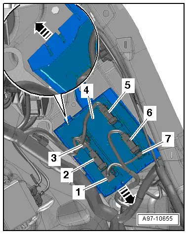
- To disconnect the connector, press the retainer -1-, turn the bracket in direction of -arrow- and disconnect the connector.
- Remove the Comfort System Central Control Module -J393-.
Vehicle Positioning System Interface Control Module -J843-, Removing and Installing
- Push the luggage compartment trim panel near the "D-pillar" to the side.
- Disconnect the control module connectors.
- Unlock and remove the expanding clips. Then remove the control module.
Fuel Filler Door Unlock Motor -V155-, Removing and Installing
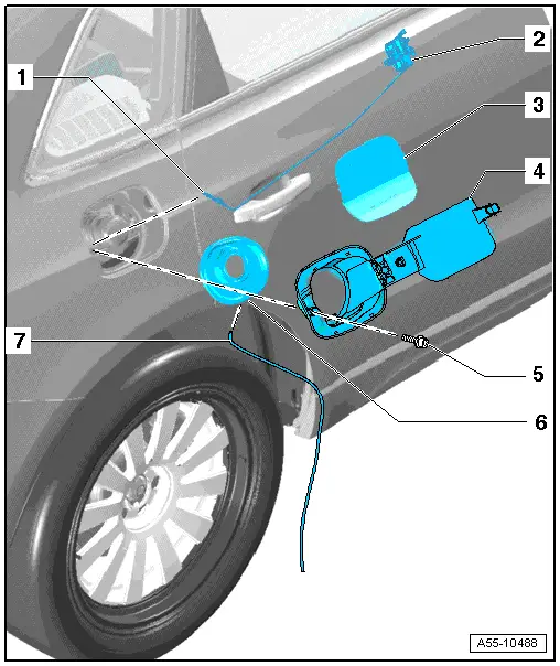
1 - Emergency Release Cable
- Routing, refer to -3- .
2 - Fuel Filler Door Unlock Motor -V155-
- Removing:
- The fuel filler door is removed. Refer to → Chapter "Overview - Fuel Filler Door Unit".
- Pull the Comfort System Central Control Module -J393- into the luggage compartment and pull it forward.
- Remove the Fuel Filler Door Unlock Motor -V155- forward off the body flange and disconnect the electrical connector.
- Installing:
- Slide the Fuel Filler Door Unlock Motor -V155- onto the flange and slide the emergency release into the luggage compartment.
3 - Fuel Filler Door Cover
- Removing.
4 - Fuel Filler Door
- Removing. Refer to → Chapter "Overview - Fuel Filler Door Unit".
5 - Bolt
- 1.7 Nm
6 - Fuel Filler Door Cup
7 - Drain Hose
Fuel Filler Door Emergency Release
1 - Fuel Filler Door Unlock Motor -V155-
2 - Comfort System Central Control Module -J393-
3 - Emergency Release Cable
- Insert the Fuel Filler Door Unlock -V 155- ash sown with the cable over the tank opening.
- Pull the cable back into the vehicle interior and connect it with the tab on the flange on the Comfort System Central Control Module -J393-.
Special Tools
Special tools and workshop equipment required
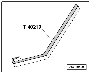
- Window Slot Seal Tool - T40219-, quantity: 3
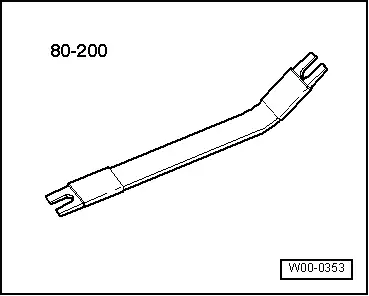
- Pry Lever -80 - 200-
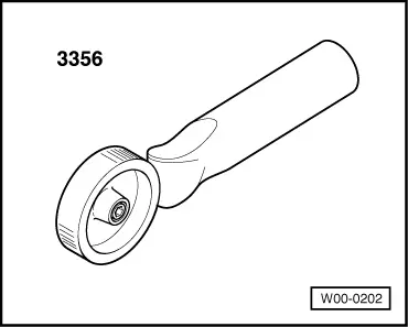
- Roller -3356-
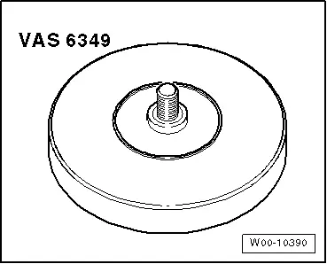
- Adhesive Strip Remover -VAS6349-
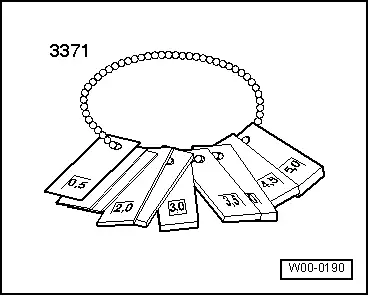
- Gauge - Gap Adjustment -3371-
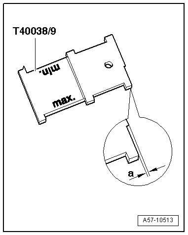
- Door Template - T40038 /9-