Audi Q5: Cockpit
General illustration
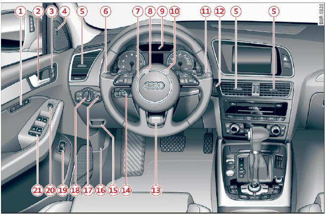
Fig. 1 Cockpit: left section
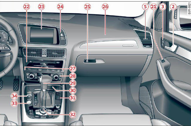
Fig. 2 Cockpit: right section
- Memory buttons (driver's seat)
- Door handle
- Power locking switch
- Side assist button
- Air outlets
- Turn signal and high beam
- Multifunction steering wheel with:
- Horn
- Driver's airbag
- Audio/video, telephone, navigation and voice recognition buttons
- Rocker switches for tiptronic operation
-
 button
 - Instrument cluster
- Reset button for trip odometer
- Switches for:
- Windshield wiper/washer
- Trip computer
- Ignition lock
- Adjustable steering column
- Control lever for:
- Cruise control
- Adaptive cruise control
- Data Link Connector for On Board Diagnostics (OBD II)
- Release lever for the engine hood
- Instrument illumination
- Light switch
- Switch for unlocking the trunk lid
- Adjuster control for outside mirrors
- Power window switches
- Radio system or Audi multimedia (see separate manual)
- Radio or MMI display (see separate manual)
- Button/Indicator light for:
- Emergency flasher
- PASSENGER AIR BAG OFF
- Glove compartment (lockable)
- Front passenger's airbag
- Depending on options
- Audi drive select button
- Start-Stop-System button or
-
 button
(hybrid drive)
button
(hybrid drive) - Parking system button
- Electronic Stabilization Control (ESC) button
- Hill descent assist button
- Climate control
- Shift lever for automatic transmission
- Coin storage
- Depending on options:
- MMI control console or
- Parking system button
- Electronic Stabilization Control (ESC) button
- Hill descent assist button
- Audi drive select button
- Start-Stop-System button
-
 button
 - Electromechanical parking brake
Tips
Some of the equipment or features shown in the general illustration may be standard equipment on your vehicle or may be optional equipment depending on your model. Always ask your authorized Audi dealer if you have a question about your vehicle.

