Audi Q5: Shock Absorber, Servicing
Shock Absorber, FWD, Servicing
Special tools and workshop equipment required
- Torque Wrench 1332 40-200Nm -VAG1332-
- Shock Absorber Set -T10001-
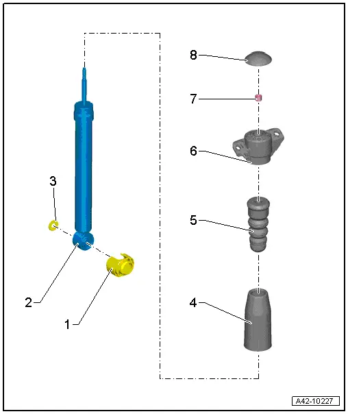
1 - Stone Chip Protection
2 - Shock Absorber
- Only shock absorbers with the same part number may be installed on the left and right
- Removing and installing. Refer to → Chapter "Shock Absorber, AWD, Removing and Installing"
- There are different versions of the suspension. Refer to → Chapter "Explanations of Production Control Numbers (PR Number)".
- Always vent and drain faulty shock absorbers before disposal. Refer to → Chapter "Rear Shock Absorbers, Venting and Emptying".
- Shock Absorber, Checking. Refer to → Chapter "Repair Information".
3 - Washer
- Always use
4 - Protective Pipe
5 - Stop Buffer
6 - Upper Shock Absorber Mount
- Installed position.
7 - Nut
- 35 Nm
- Always replace if removed
- Loosening and Tightening.
8 - Cover
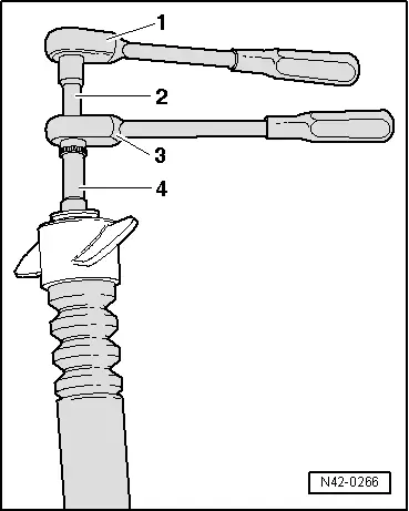
Loosening and tightening the nut
1 - Ratchet (commercially available)
2 - Shock Absorber Set - Extension with Counter Holder 1 -T10001/9-
3 - Shock Absorber Set - Reversible Ratchet -T10001/11-
4 - Shock Absorber Set - Socket -T10001/1-
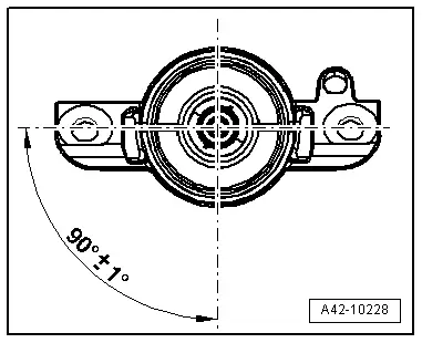
Upper shock absorber mount installation position
- Install the upper shock absorber mount so it is rotated 90º to the lower shock absorber mount.
Shock Absorber, AWD, Servicing
Special tools and workshop equipment required
- Torque Wrench 1332 40-200Nm -VAG1332-
- Shock Absorber Set -T10001-
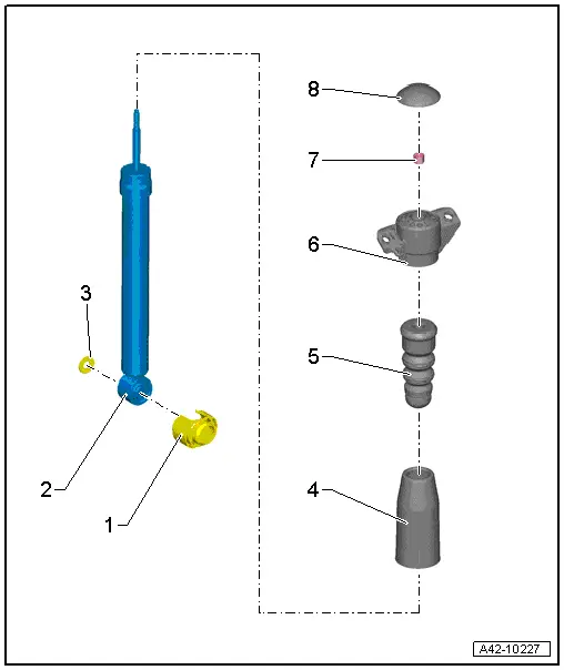
1 - Stone Chip Protection
2 - Shock Absorber
- Only shock absorbers with the same part number may be installed on the left and right
- Removing and installing. Refer to → Chapter "Shock Absorber, AWD, Removing and Installing"
- There are different versions of the suspension. Refer to → Chapter "Explanations of Production Control Numbers (PR Number)".
- Always vent and drain faulty shock absorbers before disposal. Refer to → Chapter "Rear Shock Absorbers, Venting and Emptying".
- Shock Absorber, Checking. Refer to → Chapter "Shock Absorbers, Checking when Removed".
3 - Washer
- Always use
4 - Protective Pipe
5 - Stop Buffer
6 - Upper Shock Absorber Mount
- Installed position. Refer to → Fig. "Upper shock absorber mount installation position"
7 - Nut
- 35 Nm
- Always replace if removed
- Loosening and Tightening. Refer to → Fig. "Loosening and tightening the nut"
8 - Cover
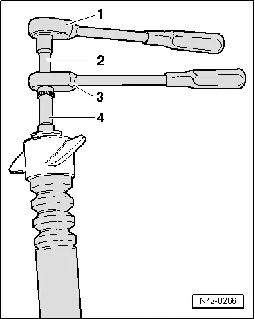
Loosening and tightening the nut
1 - Ratchet (commercially available)
2 - Shock Absorber Set - Extension with Counter Holder 1 -T10001/9-
3 - Shock Absorber Set - Reversible Ratchet -T10001/11-
4 - Shock Absorber Set - Socket -T10001/1-
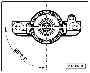
Upper shock absorber mount installation position
- Install the upper shock absorber mount so it is rotated 90º to the lower shock absorber mount.