Audi Q5: Input Shaft Seal, Replacing, 0BD
- The flange/driveshaft used before must be installed.
- If the flange/driveshaft is also being replaced, do the following. Refer to → Chapter "Flange Shaft Ring, Replacing, 0BD".
Special tools and workshop equipment required
- Puller - Multiple Use -VW391-
- Slide Hammer Set -VW771-
- Slide Hammer Set - Hook -VW771/37-
- Seal Installer - Driveshaft Flange - T40112-
- Retainer - Drive Flange - 3028-
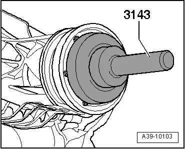
- Seal Installer - Wheel Bearing Seal - 3143-
- Holding Fixture - Gearbox Adapter -T10235-
- Friction Gauge - VAS6222-
- Inductive Heater -VAS6414-
- Sealing Grease -G 052 128 A1-
- Locking Fluid - AMV 185 101 A1-
- Three M8 x 25 bolts
- Two M10 x 40 bolts
Removing
- The flange/driveshaft seal can replaced only when the rear final drive is removed.
Pay attention to the general repair information. Refer to → Chapter "Repair Information".
- Remove the rear final drive. Refer to → Chapter "Final Drive, Removing and Installing".
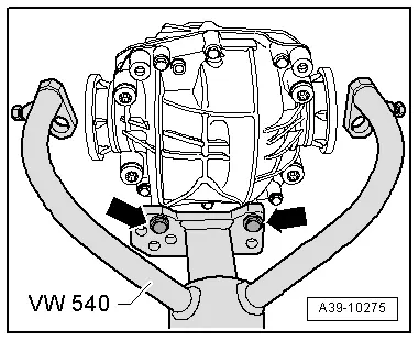
- Secure the rear final drive to the Holding Fixture -VW540- using the bolts (M10 x 40) -arrows-.
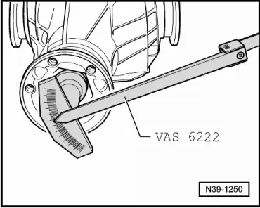
- Measure the friction torque before loosening the pinion nut.
- Write down this value.
 Caution
If, during the repair, the flange/driveshaft must be replaced, then this measured must be adjusted once again. Refer to → Chapter "Flange Shaft Ring, Replacing, 0BD".
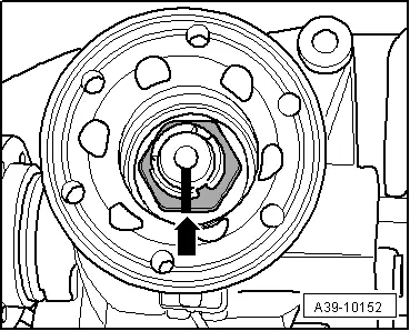
- Mark the position of the drive pinion nut to the drive pinion -arrow-.

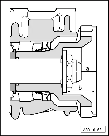
Determining dimension "-a-" and dimension "-b-"
- Flange distance to the pinion = dimension -a-
- Distance from the flange to the drive pinion nut = dimension -b-
- Write down the established dimensions.
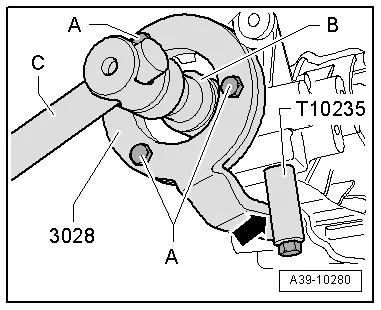
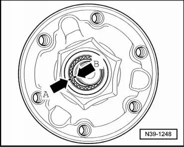
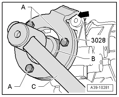
- Secure the Retainer - Drive Flange -3028- to the flange/driveshaft with the bolts -A-.
- Secure the Holding Fixture - Gearbox Adapter -T10235- in the threaded hole below the flange/driveshaft.
- Loosen the pinion nut, at the same time the Retainer - Drive Flange -3028- must be supported on the Holding Fixture - Gearbox Adapter -T10235--arrow-.
- Count the number of turns when removing the drive pinion nut and write it down.
-A -Three M 8 x 25 bolts
-B -32 mm Socket
-C -Toggle
- Mark the position of the flange/driveshaft -arrow A- to the drive pinion -arrow B-.
- Place the Drip Tray underneath.
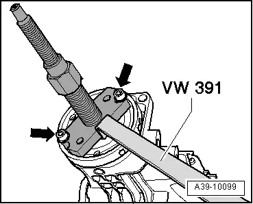
- Secure the Puller - Multiple Use -VW391- using the Two bolts M 8 x 25 -arrows-.
- Remove the flange/driveshaft.
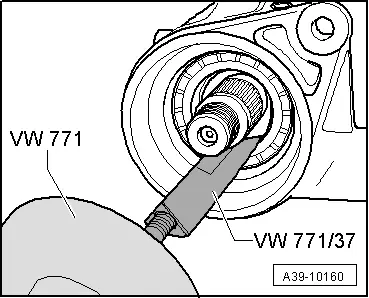
- Remove the shaft seal.
- Clean the threads on the drive pinion.
Installing
Install in reverse order of removal. Note the following:
- Coat outer edge of the seal with gear oil.
- Fill the space between the sealing/dust lip halfway with Sealing Grease -G 052 128 A1-.
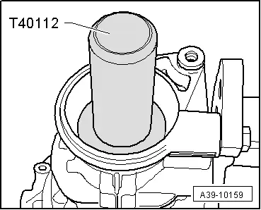
- Drive in new shaft seal as far as stop without tilting it.
- Warm the flange/driveshaft to approximately 80 ℃ (176 ºF) using an Inductive Heater -VAS6414-.
- Align the markings on the flange/driveshaft -arrow A- and the drive pinion -arrow B-.

- Install the flange/driveshaft.
- Insert the old pinion nut with Locking Fluid -AMV 185 101 A1-.
- Secure the Retainer - Drive Flange -3028- to the flange/driveshaft with the bolts -A-.
- When tightening the pinion nut, the Retainer - Drive Flange -3028- must be supported on the housing brace -arrow-.
-A -Three M 8 x 25 bolts
-B -32 mm Socket
-C -Toggle
- Install the drive pinion nut using the number of turns noted earlier and tighten to the position marked -arrow-.
Perform the measuring check - check dimension -a- and dimension -b-.
- The measurement may differ by +- 0.2 mm.
- Install the rear final drive. Refer to → Chapter "Final Drive, Removing and Installing".
- Check the gear oil in rear final drive. Refer to → Chapter "Gear Oil, Checking Level, 0BD".


