Audi Q5: Overview - Rearview Camera System
The rear view camera system assists the driver during backup driving by providing the driver with an image of the traffic situation behind the vehicle via the Front Information Display Control Head -J685-.
The rear view camera system is switched on when engaging the reverse gear. The system can be activated manually by pressing the Parking Aid Button -E266- in the center console (optional).
The rear view camera system consists of the following components:
- Rearview Camera -R189-
- Rearview Camera System Control Module -J772-
- Information Electronics Control Module 1 -J794-
- Steering wheel with Steering Angle Sensor -G85-
Other control modules may be installed as optional equipment.
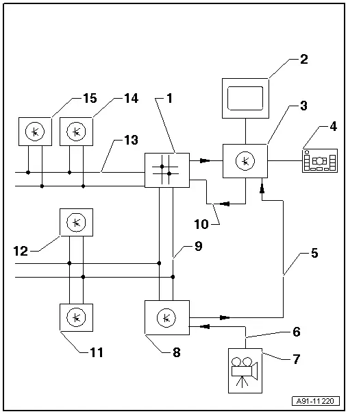
1 - Data Bus On Board Diagnostic Interface -J533- Behind the Glove Compartment On the Left Side
2 - Front Information Display Control Head -J685- in center of the instrument panel
3 - Information Electronics Control Module 1 -J794- inside the instrument panel
4 - Multimedia System Control Head -E380- in the center console
5 - CVBS cable from the Rearview Camera System Control Module -J772-
6 - CVBS cable from Rearview Camera -R189-
7 - Rearview Camera -R189- in the rear lid
8 - Rearview Camera System Control Module -J772- behind the luggage compartment trim panel on the left side
9 - CAN Bus (comfort)
10 - MOST Bus
11 - Parking Aid Control Module -J446- behind the right luggage compartment trim panel
12 - Towing Recognition Control Module -J345- behind the right luggage compartment trim panel
13 - CAN Bus (powertrain)
14 - ABS Control Module -J104- in the engine compartment
15 - Steering Angle Sensor -G85- on steering column at Steering Column Electronic Systems Control Module -J527-
It is not permitted to install an auxiliary license plate for vehicles with rear view camera system as it could impair the function of the rear view camera system.
Perform the Fault Finding with the Vehicle Diagnostic Tester.
Component Location Overview - Rearview Camera System
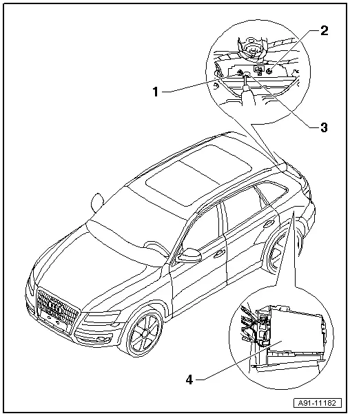
1 - Nut
- 6 Nm
2 - Nut
- 6 Nm
3 - Rearview Camera -R189-
- In the rear lid handle
- Removing and installing. Refer to → Chapter "Rearview Camera -R189-, Removing and Installing".
- Calibrating. Refer to → Chapter "Rearview Camera System, Calibrating".
4 - Rearview Camera System Control Module -J772-
- Behind the left luggage compartment trim panel
- Connector assignment. Refer to → Chapter "Rearview Camera System Control Module -J772- Connectors".
- Removing and installing. Refer to → Chapter "Rearview Camera System Control Module -J772-, Removing and Installing".
- Calibrating. Refer to → Chapter "Rearview Camera System, Calibrating".

