Audi Q5: Rearview Camera -R189-, Removing and Installing
The Rearview Camera -R189- is inside the rear lid handle button. It permanently attached to the button.
If the Rearview Camera -R189- must be replaced, then the handle button must also be replaced.
- Turn off the ignition and all electrical consumers and remove the ignition key.
 WARNING
Danger of unintended engine ignition
Turn off the ignition and remove the ignition key from the vehicle interior for all work performed on the high voltage vehicle.
Removing
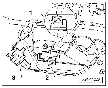
The Rearview Camera -R189- has a trailing cable. The vehicle wiring harness couplings are located in the rear lid.
- Remove the rear lid trim panel. Refer to → Body Interior; Rep. Gr.70; Luggage Compartment Trim Panels; Lower Rear Lid Trim Panel, Removing and Installing.
- Disconnect the connectors -1-, -2- and -3- in the rear lid and on the handle button.
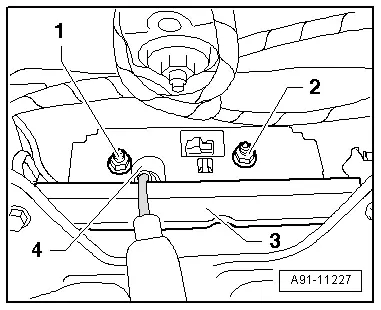
The Rearview Camera -R189- is firmly attached to the handle button -4-.
- Remove nuts -1- and -2-.
- Pull the handle button -4- and Rearview Camera -R189- out of the retainer -3- inside the rear lid.
Installing
- Install in reverse order of removal.
- Close the rear lid.
- Perform the calibration. Refer to → Chapter "Rearview Camera System, Calibrating".
Tightening specifications and installation instructions can be found in the Component Location Overview. Refer to → Chapter "Component Location Overview - Rearview Camera System".