Audi Q5: Tie Rod, Removing and Installing
Special tools and workshop equipment required
- Torque Wrench 1332 40-200Nm -VAG1332-
- Track Rod Tool Insert -T40183-
- No illustration, commercially available pawl with fine gear
Removing
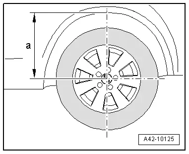
- Determine dimension -a- from the center of the wheel to the lower edge of the wheel housing before starting work while the vehicle is resting on its wheels.
- Place the vehicle on a hoist.
- Remove the wheel.
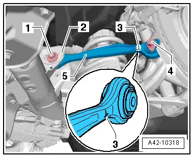
- Remove the bolt -4-.
- Mark the position of the bolt -1- to the subframe -2-.
- Remove the nut and the bolt -1-.
- Remove the tie rod -5-.
Installing
Install in reverse order of removal. Note the following:
 Note
Note
- Bonded rubber bushings have a limited range of motion. Only tighten suspension screws when vehicle is in curb weight or control position.
- Wheel bearing, lifting to curb weight position on vehicles with coil springs. Refer to → Chapter "Wheel Bearing in Curb Weight, Lifting Vehicles with Coil Spring".
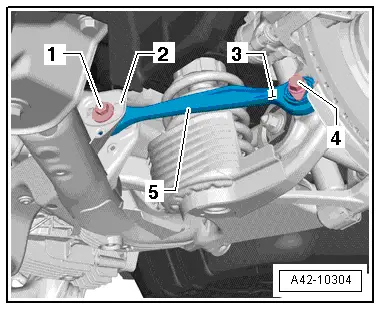
- Insert the tie rod -5-.
The marking -3- (one on the "head of the T") on the tie rod -5- must be on the out the outer side pointing forward, as illustrated.
- First insert the bolt -1- completely and then align it according the marking.
- Insert and tighten the bolt -4-.
- Install the bolt -1- by hand. Tighten the bolt nut -1- to the tightening specification only after measuring the axle alignment.
- Tighten the wheel. Refer to → Chapter "Wheel Bolt Tightening Specifications".
- An axle alignment may be required. Refer to → Chapter "Evaluating Need for Axle Alignment".