Audi Q5: Overview - Transmission
Audi Q5 Type 8R (2008 - 2017) Service Manual / Transmission / General, Technical data / Overview - Transmission
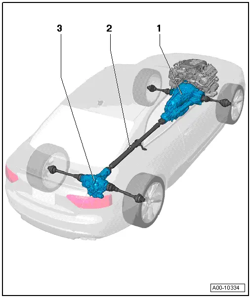
1 - Transmission
2 - Driveshaft
- Overview. Refer to → Chapter "Overview - Driveshaft".
- Removing and installing. Refer to → Chapter "Driveshaft, Removing and Installing".
3 - Rear Final Drive
- Removing and installing. Refer to → Chapter "Final Drive".
- Disassembling and assembling. Refer to → Chapter "Final Drive, Disassembling and Assembling".
Electrical Components
Component Location Overview - Electrical Components
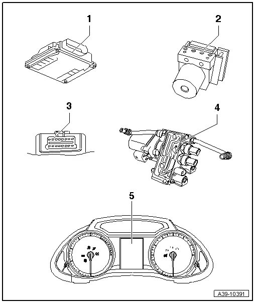
1 - All Wheel Drive Control Module -J492-
- Component location A4 Sedan, A5 Coupe and A5 Cabriolet. Refer to → Fig. " All Wheel Drive Control Module -J492- in the A4 Sedan, A5 Coupe and the A5 Cabriolet".
- Component location A4 Avant. Refer to → Fig. " All Wheel Drive Control Module -J492- in the A4 Avant".
- Component location A5 Sportback. Refer to → Fig. " All Wheel Drive Control Module -J492- in the A5 Sportback".
- Component location A6 and A7. Refer to → Fig. " All Wheel Drive Control Module -J492- in the Audi A6/A7".
- Component location A8. Refer to → Fig. " All Wheel Drive Control Module -J492- in the A8".
- Removing and installing. Refer to → Chapter "All Wheel Drive Control Module -J492-, Removing and Installing".
- Additional work after replacing the control module. Refer to → Chapter "All Wheel Drive Control Module -J492-, Additional Work after Replacing".
- Important signals from engine control module and ABS Control Module -J104- are transmitted via the Data bus to the All Wheel Drive Control Module.
2 - ABS Control Module -J104-
- Installed location, removing and installing. Refer to → Brake System; Rep. Gr.45; Component Location Overview.
3 - Diagnostic Connection
- Installed location: Driver side footwell. Refer to → Fig. "Diagnostic Connection".
- Vehicle Diagnostic Tester, Connecting and Selecting Functions
4 - Hydraulic Control Unit
- Component location: on rear final drive
- Removing and installing. Refer to → Chapter "Hydraulic Control Unit, Removing and Installing".
- Disassembling and assembling. Refer to → Chapter "Hydraulic Control Unit, Disassembling and Assembling".
- Hydraulic control unit with:
- All Wheel Drive Pump -V415-. Refer to → Chapter "All Wheel Drive Pump -V415-, Removing and Installing".
- Oil Pressure/Temperature Sensor 2 -G640-. Refer to → Chapter "Oil Pressure/Temperature Sensor -G437- or Oil Pressure/Temperature Sensor 2 -G640-, Removing and Installing".
- Oil Pressure/Temperature Sensor -G437-. Refer to → Chapter "Oil Pressure/Temperature Sensor -G437- or Oil Pressure/Temperature Sensor 2 -G640-, Removing and Installing".
- All Wheel Drive Clutch Valve 2 -N446-. Refer to → Chapter "All Wheel Drive Clutch Valve -N445- or All Wheel Drive Clutch Valve 2 -N446-, Removing and Installing".
- All Wheel Drive Clutch Valve -N445-. Refer to → Chapter "All Wheel Drive Clutch Valve -N445- or All Wheel Drive Clutch Valve 2 -N446-, Removing and Installing".
5 - Display in Instrument Cluster

