Audi Q5: Radio Connector Assignment, MMI
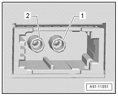
Radio -R-
1 - (AM/FM1/FM2) antenna jack
2 - Black Antenna Connection (Satellite Tuner) from Roof Antenna -R216- (Satellite Antenna -R170-)
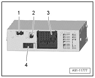
3 - Connection block with four multipin connectors
4 - MOST Bus
 Note
Note
Unlisted connector terminals are not assigned.
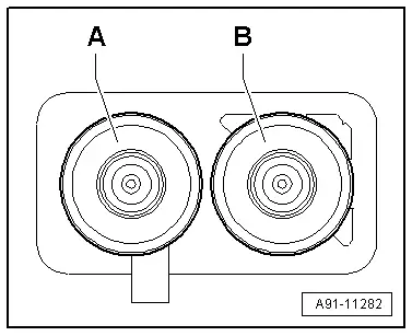
1 - AM/FM1/FM2 antenna connection
A - AM/FM1 Chamber 2 from the Antenna Amplifier 3 -R112- (Radio Antenna 2 -R93-)
B - Chamber 1 (FM2) from Antenna Amplifier -R24- (Antenna -R11-)
3 - Connection block with four multipin connectors
A - Brown 8-pin connector (T8ag)
1 - Right rear speaker (+)
2 - Right front speaker (+)
3 - Left front speaker (+)
4 - Left rear speaker (+)
5 - Right rear speaker (-)
6 - Right front speaker (-)
7 - Left front speaker (-)
8 - Left rear speaker (-)

B - Blue 12-pin connector (T12w)
17 - Left LF-In
18 - LF-In ground
19 - LF-In diag
21 - LF diag
22 - LF (-)
23 - Right LF-In
24 - LF-In ground shielding
27 - LF ground shielding
28 - LF (+)
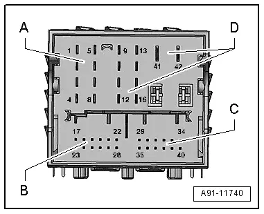
C - multipin connector, 12-pin
29 - Headphones output 1 Diag
31 - Headphones output 1/2 Diag
34 - Headphones output 2 Diag
35 - Headphones output 1 left
36 - Headphones output 1 ground
37 - Headphones output 1 right
38 - Headphones output 2 left
39 - Headphones output 2 ground
40 - Headphones output 1 right

D - Black 10-pin connector (T16ag)
9 - Subwoofer in Rear Shelf -R157-
10 - Center Mid-Treble Speaker -R158-
11 - Ring-break Diagnostic Cable
13 - Subwoofer in Rear Shelf -R157-
14 - Center Mid-Treble Speaker -R158-
41 - Terminal 31
42 - Terminal 30

4 - MOST Bus
1 - Input
2 - Output