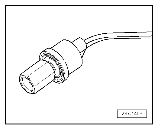
Audi Q5: A/C Refrigerant High Pressure Switch -F23-
 Note
Note
Switch pressures, removing and installing switches as well as switch arrangement and version. Refer to vehicle specific refrigerant circuit → Heating, Ventilation and Air Conditioning; Rep. Gr.87; System Overview - Refrigerant Circuit (vehicle-specific repair manual).
Function:
Switches the coolant fan to the next higher level when the pressure in the refrigerant circuit increases (approximately 16 bar (232 psi) ).
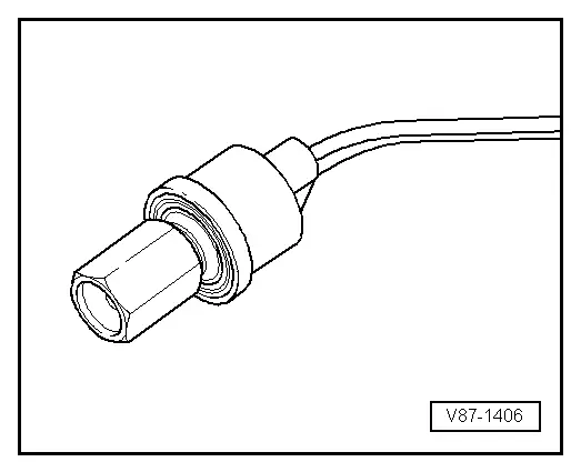
Magnetic Clutch High Pressure Switch -F118-
 Note
Note
Switch pressures, removing and installing switches as well as switch arrangement and version. Refer to vehicle specific refrigerant circuit → Heating, Ventilation and Air Conditioning; Rep. Gr.87; System Overview - Refrigerant Circuit (vehicle-specific repair manual).
Function:
Switches off A/C compressor when there is excessive pressure in the refrigerant circuit (approximately 32 bar (464 psi) ).
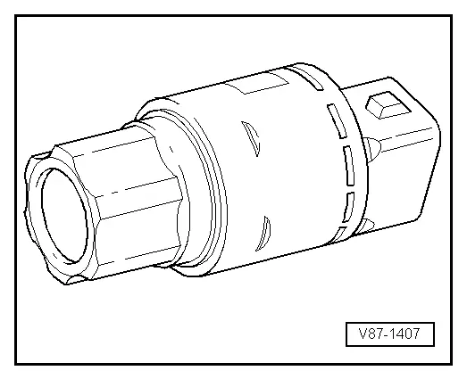
A/C Refrigerant Low Pressure Switch -F73-
 Note
Note
Switch pressures, removing and installing switches as well as switch arrangement and version. Refer to vehicle specific refrigerant circuit → Heating, Ventilation and Air Conditioning; Rep. Gr.87; System Overview - Refrigerant Circuit (vehicle-specific repair manual).
Function:
Switches off A/C compressor when there is excessive pressure in the refrigerant circuit (approximately 2 bar (29 psi) ).
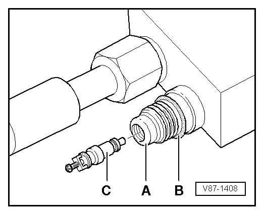
Refrigerant Circuit Connections with Valve for Switches
 Note
Note
Switch pressures, removing and installing switches as well as switch arrangement and version. Refer to vehicle specific refrigerant circuit → Heating, Ventilation and Air Conditioning; Rep. Gr.87; System Overview - Refrigerant Circuit (vehicle-specific repair manual).
- Different threads for switch on high pressure and low pressure sides.
- Only valves and O-ring seals that are resistant to refrigerant R134a and refrigerant oil must be installed.
A - Connection (soldered in)
B - O-ring seal
C - Valve (with O-ring seal)
 Note
Note
To remove and install the valve insert -C- when the refrigerant circuit is discharged, use, for example, an adapter from the Refrigerant Sockets -T10364- (for the tightening specification. Refer to → Chapter "Connections with Schrader Valve (Needle Valve)").