Audi Q5: Battery Charger -VAS5903-
Audi Q5 Type 8R (2008 - 2017) Service Manual / Electrical System / Electrical Equipment General Information / Battery, Starter, Generator, Cruise Control / Battery Charger -VAS5903-
 WARNING
Risk of injury. Follow all warning messages and safety precautions. Refer to → Chapter "Warnings and Safety Precautions".
 WARNING
Do not check or charge a Battery -A- when the visual indicator has "no color or is bright yellow". Jump starting must not be used!
There is a risk of explosion during testing, charging or jump starting.
These Batteries -A- must be replaced.
 Note
Note
Observe the Battery Charger -VAS5903- Operating Instructions.
- Battery Charger -VAS5903- device description. Refer to → Chapter "Battery Charger -VAS5903- Device Description".
- Charge the Battery -A-. Refer to → Chapter "Battery, Charging with Battery Charger -VAS5903-".
- Refresh charging. Refer to → Chapter "Refresh Charging with Battery Charger -VAS5903-".
- Severely discharged Battery -A-, charging. Refer to → Chapter "Severely Discharged Battery, Charging with Battery Charger -VAS5903-".
- Support mode. Refer to → Chapter "Battery Charger -VAS5903- Support Mode".
- Maintenance charging. Refer to → Chapter "Battery Charger -VAS5903- Maintenance Charging".
Battery Charger -VAS5903- Device Description
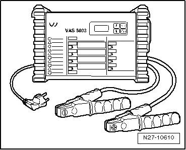
The Battery Charger -VAS5903- is designed to charge all 12 V Batteries -A- in the VW group.
Battery Charger -VAS5903-
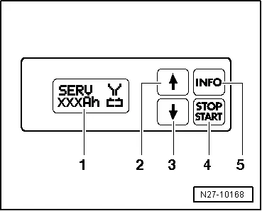
Control Field Overview
1 - Display
2 - ↑-button "Up"
3 - ↓-button "Down"
4 - START/STOP-button
5 - INFO-button