Audi Q5: Connector Assignments
Sound System Connector Assignments Standard, CAN
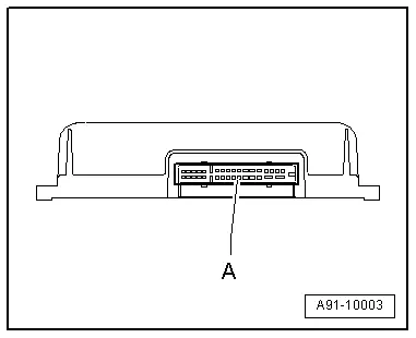
Digital Sound System Control Module -J525-
A - Black 32-pin connector (T32h)
 Note
Note
Unlisted connector terminals are not assigned.
A - Black 32-pin connector (T32h)
1 - Terminal 30
2 - Terminal 31
3 - Subwoofer in Rear Shelf -R157- (+)
4 - Left Front Speaker (+)
5 - Right Front Speaker (-)
6 - Left Rear Speaker (+)
7 - Right Rear Speaker (+)
8 - Center Mid-Treble Speaker -R158- (+)
13 - CAN Bus high (Infotainment)
14 - CAN Bus low (Infotainment)
15 - Subwoofer in Rear Shelf -R157- (-)
16 - Left Front Speaker (+)
17 - Right Front Speaker (-)
18 - Left Rear Speaker (-)
19 - Right Rear Speaker (-)
20 - Center Mid-Treble Speaker -R158- (-)
23 - Right Rear Signal (+) from Radio -R-
24 - Left Rear Signal (+) from Radio -R-
25 - Right Front Signal (+) from Radio -R-
26 - Left Front Signal (+) from Radio -R-
28 - Right Rear Signal (-) from Radio -R-
29 - Left Rear Signal (-) from Radio -R-
30 - Right Front Signal (-) from Radio -R-
31 - Left Front Signal (-) from Radio -R-

Sound System Connector Assignments, Bang & Olufsen, CAN
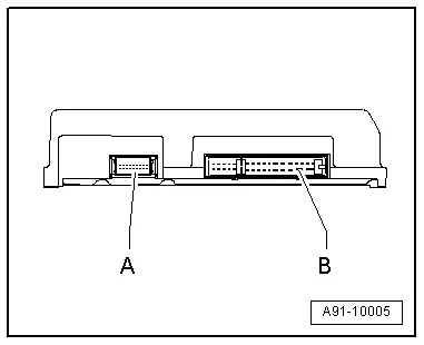
Digital Sound System Control Module -J525-
A - Black 18-pin connector (T18b)
B - Black 32-pin connector (T32h)
 Note
Note
Unlisted connector terminals are not assigned.
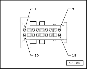
A - Black 18-pin connector (T18b)
1 - Microphone input 1 (+) from Microphone Unit In Front Roof Module -R164- (Interior Microphone -R74-)
2 - Microphone input 1 (Ground Shielding) from Microphone Unit In Front Roof Module -R164- (Interior Microphone -R74-)
3 - Not Assigned
4 - Right Rear Signal (+) from Radio -R-
5 - Left Rear Signal (+) from Radio -R-
6 - Right Front Signal (+) from Radio -R-
7 - Left Front Signal (+) from Radio -R-
8 - Not Assigned
9 - CAN Bus high (Infotainment)
10 - Microphone input 1 (-) from Microphone Unit In Front Roof Module -R164- (Interior Microphone -R74-)
11 - Not Assigned
12 - Not Assigned
13 - Right Rear Signal (-) from Radio -R-
14 - Left Rear Signal (-) from Radio -R-
15 - Right Front Signal (-) from Radio -R-
16 - Left Front Signal (-) from Radio -R-
17 - Not Assigned
18 - CAN Bus low (Infotainment)
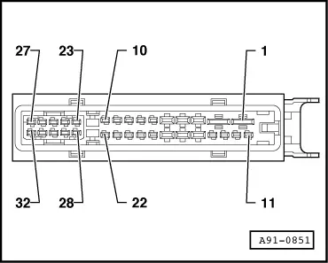
B - Black 32-pin connector (T32h)
1 - Terminal 30
2 - Terminal 31
3 - Left Rear Speaker (+)
4 - Right Rear Speaker (+)
5 - Center Mid-Treble Speaker -R158- (+)
6 - Left Front Speaker (+)
7 - Right Front Speaker (-)
8 - Left Rear Midrange Speaker -R105- (+)
9 - Right Rear Midrange Speaker -R106- (+)
10 - Right Front Bass Speaker -R23- (+)
15 - Left Rear Speaker (-)
16 - Right Rear Speaker (-)
17 - Center Mid-Treble Speaker -R158- (-)
18 - Left Front Speaker (+)
19 - Right Front Speaker (-)
20 - Left Rear Midrange Speaker -R105- (-)
21 - Right Rear Midrange Speaker -R106- (-)
22 - Right Front Bass Speaker -R23- (-)
23 - Left Front Bass Speaker -R21- (+)
25 - Subwoofer in Rear Shelf -R157- (+)
28 - Left Front Bass Speaker -R21- (-)
30 - Subwoofer in Rear Shelf -R157- (-)
Sound System Connector Assignments, Bang & Olufsen, MMI
Digital Sound System Control Module -J525-
A - MOST Bus
B - Black 18-pin connector (T18b)
C - Black 32-pin connector (T32h)
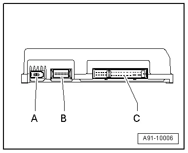
 Note
Note
Unlisted connector terminals are not assigned.
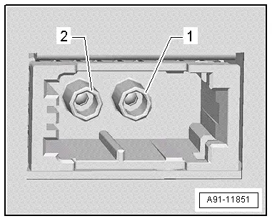
A - MOST Bus
1 - Input
2 - Output
B - Black 18-pin connector (T18b)
1 - Microphone input 1 (+) from Microphone Unit In Front Roof Module -R164- (Interior Microphone -R74-)
2 - Microphone input 1 (Ground Shielding) from Microphone Unit In Front Roof Module -R164- (Interior Microphone -R74-)
10 - Microphone input 1 (-) from Microphone Unit In Front Roof Module -R164- (Interior Microphone -R74-)
17 - Ring-break Diagnostic Cable

C - Black 32-pin connector (T32h)
1 - Terminal 30
2 - Terminal 31
3 - Left Rear Speaker (+)
4 - Right Rear Speaker (+)
5 - Center Mid-Treble Speaker -R158- (+)
6 - Left Front Speaker (+)
7 - Right Front Speaker (-)
8 - Left Rear Midrange Speaker -R105- (+)
9 - Right Rear Midrange Speaker -R106- (+)
10 - Right Front Bass Speaker -R23- (+)
15 - Left Rear Speaker (-)
16 - Right Rear Speaker (-)
17 - Center Mid-Treble Speaker -R158- (-)
18 - Left Front Speaker (+)
19 - Right Front Speaker (-)
20 - Left Rear Midrange Speaker -R105- (-)
21 - Right Rear Midrange Speaker -R106- (-)
22 - Right Front Bass Speaker -R23- (-)
23 - Left Front Bass Speaker -R21- (+)
25 - Subwoofer in Rear Shelf -R157- (+)
28 - Left Front Bass Speaker -R21- (-)
30 - Subwoofer in Rear Shelf -R157- (-)


