Audi Q5: Overview - Antenna Systems
Audi Q5 Type 8R (2008 - 2017) Service Manual / Electrical System / Communication / Antenna Systems / Overview - Antenna Systems
The antenna system consists of the window antennas and the roof antenna.
Window Antennas
- Digital Radio Antenna - R183- (DAB) Left Antenna Module -R108- on the left D-pillar (Europe only)
- Radio Antenna 2 -R93- (FM2)/Central Locking and Anti-Theft Alarm System Antenna -R47- (CLS) Antenna Amplifier -R24- at the bottom of the rear lid on the left side (CAN)
- Radio Antenna 2 -R93- (AM/FM1)/Central Locking and Anti-Theft Alarm System Antenna -R47- (CLS) Antenna Amplifier -R24- at the bottom of the rear lid on the left side (MMI)
- Antenna -R11- (AM/FM1) Antenna Amplifier 3 -R112- at the top of the rear lid on the left side (CAN)
- Antenna -R11- (FM2)/TV Antenna 1 -R55- (TV1) Antenna Amplifier 3 -R112- at the top of the rear lid on the left side (MMI)
- TV Antenna 2 - R56- (TV2)/TV Antenna 3 -R57- (TV3) Antenna Amplifier 4 - R113- at the bottom of the rear lid on the right side (MMI).
Roof Antenna -R216-
- GPS Antenna -R50-
- Telephone Antenna -R65-
- Auxiliary Heater Antenna -R182-
- Satellite Antenna -R170- only USA
The Roof Antenna -R216- with SAT connection applies only to the USA.
The Left Antenna Module -R108- with DAB connection applies only to Europe.
Repairing antenna wires. Refer to → Electrical Equipment General Information; Rep. Gr.97; Wiring Harness and Connector Repairs; Antenna Wires, Repairing.
Component Location Overview - Antenna Systems
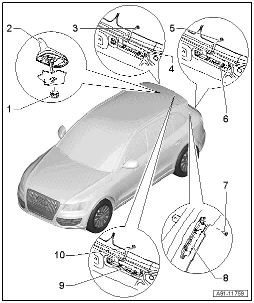
1 - Nut
- 6 Nm
2 - Roof Antenna -R216-
- Removing and installing. Refer to → Chapter "Roof Antenna -R216-, Removing and Installing".
3 - Bolt
- 2 Nm
4 - Antenna Amplifier 4 -R113-
- Connector assignment.
- Removing and installing. Refer to → Chapter "Antenna Amplifier -R24-/Antenna Amplifier 4 -R113-, Removing and Installing".
5 - Bolt
- 2 Nm
6 - Antenna Amplifier -R24-
- Connector Assignment (CAN).
- Connector assignment (MMI).
- Removing and installing. Refer to → Chapter "Antenna Amplifier -R24-/Antenna Amplifier 4 -R113-, Removing and Installing".
7 - Bolt
- 2 Nm
8 - Left Antenna Module -R108-
- Connector assignment.
- Removing and installing. Refer to → Chapter "Left Antenna Module -R108-, Removing and Installing".
9 - Antenna Amplifier 3 -R112-
- Connector Assignment (CAN).
- Connector assignment (MMI).
- Removing and installing. Refer to → Chapter "Antenna Amplifier 3 -R112-, Removing and Installing".
10 - Bolt
- 2 Nm

