Audi Q5 Owners & Service Manuals

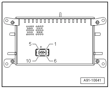
Audi Q5: Display Connector Assignment, CAN

Front Information Display Control Head -J685-

  Note

Unlisted connector terminals are not assigned.

"chorus"(T10u) red

1 - CAN Bus (display) from the Radio -R-

2 - CAN Bus (display) from the Radio -R-

3 - Voltage Supply from the Radio - R-

4 - Terminal 31

Audi Q5. A91-10642

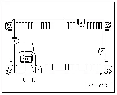
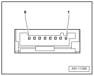
"concert"/"symphony"(T10w) black

All pins are connected to the Radio -R-.

1 - Power Supply

2 - Ground

3 - Not Assigned

4 - Diag. Display

5 - Diag. Cable

6 - LVDS OUT (+)

7 - LVDS OUT (-)

8 - LVDS ground

9 - Diag. T0

10 - Diag. T1

Audi Q5. A91-10641

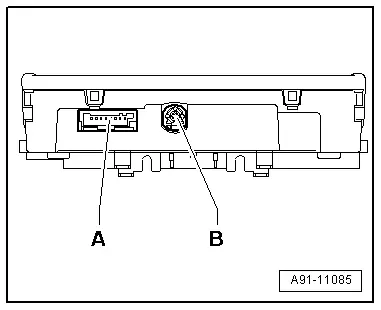
Display Connector Assignment, MMI

Front Information Display Control Head -J685-

A - Black 8-pin connector (T8ai)

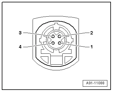
B - 4-pin connector (T4an/T4ao) from Information Electronics Control Module 1 -J794-

Audi Q5. A91-11085

  Note

Unlisted connector terminals are not assigned.

A - Black 8-pin connector (T8ai)

4 - Terminal 30

5 - Terminal 31

Audi Q5. A91-11086

B - Black/white 4-pin connector (T4an/T4ao)

All pins are connected to the Information Electronics Control Module 1 -J794-.

1 - Ground

2 - LVDS (+)

3 - Not Assigned

4 - LVDS (-)

Audi Q5. A91-11088

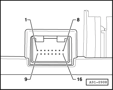
Multimedia System Control Head -E380- Connector Assignment

Multimedia System Control Head -E380-

  Note

Unlisted connector terminals are not assigned.

Multipin connector, 16-Pin

All pins are connected to the Information Electronics Control Module 1 -J794-.

6 - Wake UP

7 - Power Supply

8 - Ground

13 - RESET

14 - RESET

15 - Data

16 - Data

Audi Q5. A91-0908

    READ NEXT:

     Sound System

     Overview - Sound System

    The following systems are offered. Radio (CAN) Sound System Basic One speaker in the left and right front doors One loud speaker on the left and right side of the instrument panel Radio (CAN) Sou

     Component Location Overview - Sound System

    Component Location Overview - Sound System, Basic/Standard 1 - Left Front Treble Speaker -R20-/Right Front Treble Speaker -R22- Removing and installing. Refer to → Chapter "Front

    SEE MORE:

     Red symbols

    Fig. 23 Display: Danger symbol With a priority 1 malfunction, a red symbol appears in the upper center area of the display > fig. 23. A driver message appears as well to ex­ plain the malfunction in more detail. When this symbol appears, three warning tones sound in succession. The symbol co

     Compressor, Replacing on Account of Leakage or Internal Damage

    Vehicles with a High Voltage System (Hybrid Vehicles) Extremely Dangerous Due to High-Voltage The high-voltage system is under high-voltage. Death or serious bodily injury by electric shock. - Individuals with electronic/medical life- and health sustaining machines in or on their person canno

    © 2019-2025 Copyright www.audiq5.net