Audi Q5: Front Axle Camber, Adjusting
Camber cannot be adjusted.
Camber can be centered evenly within specified tolerance range by shifting subframe.
- Remove the noise insulation. Refer to → Body Exterior; Rep. Gr.66; Noise Insulation.
 Note
Note
- The tunnel crossmember must be loosened before adjusting the camber. Refer to → Rep. Gr.37; Subframe Mount; Overview - Subframe Mount.
- The tunnel crossmember must be loosened to prevent the transmission mount from being stressed.
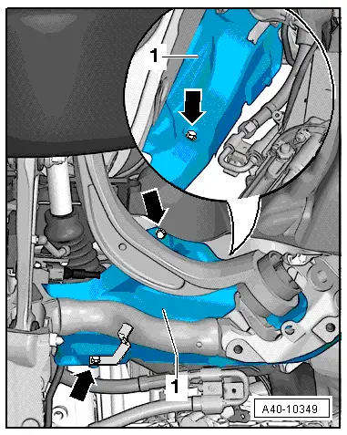
Depending on the engine version, the subframe shield must be loosened in order to be able to mount the plastic coated tire iron for moving the subframe.
- Remove the bolts -arrows-.
- Move the subframe shield -1- to the side.
- Loosen the bolts -1- through -8-.
Depending on the engine version, the following steps are necessary to loosen the bolt -1-.
- Remove the right protective joint boot, if applicable.
- Remove one wheel housing liner clip.
- Tilt the wheel housing liner to the side slightly.

 Note
Note
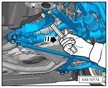
If the subframe is moved, the front of the vehicle must be lifted at the jack points using an axle lift.
- Using a plastic-coated tire iron, slide the subframe with the engine mount and stabilizer bar in the appropriate location.
Push in the center of the subframe near the lower control arm between the subframe and the body longitudinal member.
If you do not have a plastic-coated tire iron, wrap a standard tire iron in adhesive tape.
- The vehicle must be bounced several times at the front axle before checking the camber values.
 WARNING
Do not damage any parts!
Axle alignment specified values. Refer to → Chapter "Axle Alignment Specified Values".
- Tighten the bolts -2- and -3- to the specifications.
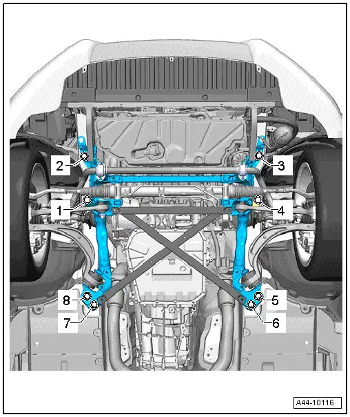
- Install the new bolts -1- and -4- one after another and tighten. Refer to → Chapter "Overview - Subframe".
- Install the new bolts -2- and -3- one after another and tighten. Refer to → Chapter "Overview - Subframe".
- Install the new bolts -8- and -5- one after another and tighten. Refer to → Chapter "Overview - Subframe".
- Install the new bolts -7- and -6- one after another and tighten. Refer to → Chapter "Overview - Subframe".
- Tighten the tunnel cross member. Refer to → Rep. Gr.37; Subframe Mount; Overview - Subframe Mount.
- Check camber value once more. Refer to → Chapter "Axle Alignment Specified Values".
- Install the right protective joint boot and the wheel housing fastener, if removed.
- Install the subframe shield, if it was removed. Tightening specifications. Refer to → Chapter "Overview - Subframe".
- Install the noise insulation. Refer to → Body Exterior; Rep. Gr.66; Noise Insulation.
CAUTION!
Every time camber is corrected, axle alignment values should be checked.
Rear Axle Camber, Adjusting
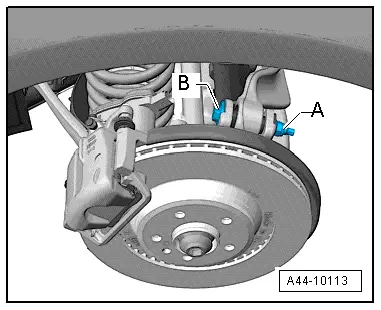
- Remove the nut -A- of threaded connection of wheel bearing housing/control arm, and screw on new nut until stop.
- Adjust the camber by rotating the adjusting bolt -B-. To turn the adjusting screw -B-, turn the hex head at the "top of the screw".
Axle alignment specified values. Refer to → Chapter "Axle Alignment Specified Values".
 Note
Note
- The maximum adjustment range is 135º to left or right of center position.
- Do not rotate the adjusting bolt -B- further once the end position has been reached or the components will be damaged.
- For a better illustration, camber adjustment is shown with wheel removed.
- Tighten nut -A--item 9-.
- After tightening nut -A-, check camber value once more. Refer to → Chapter "Axle Alignment Specified Values".
Rear Axle Toe, Adjusting
Special tools and workshop equipment required
- Track Rod Tool Insert -T40183-
- Commercially Available Pawl with Fine Gear
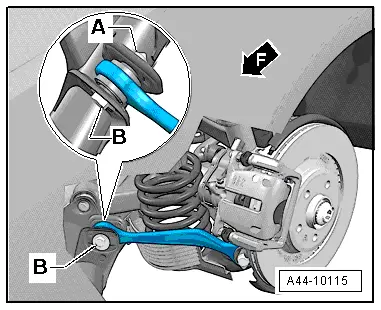
- Remove the nut -A- of threaded connection tie rod/subframe, and screw on new nut until stop.
- Adjust toe by turning eccentric screw -B-.
Axle alignment specified values. Refer to → Chapter "Axle Alignment Specified Values".
- Tighten the nut -A- using the Track Rod Tool Insert -T40183--item 25-.
- After tightening nut -A-, check toe value once more. Refer to → Chapter "Axle Alignment Specified Values".
 Note
Note
- The maximum adjustment range is 90º to left or right of center position.
- The geometric drive axle is automatically changed when individual toe settings are changed.
Front Axle Toe, Adjusting
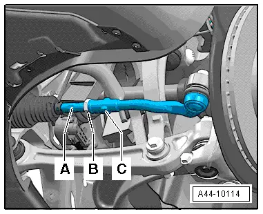
- Measure the dimension -a- between the tie rod head -1- and the left and right tie rod -2- and make a note of the value. Dimension -a- should be the same before and after adjusting on the left and right.
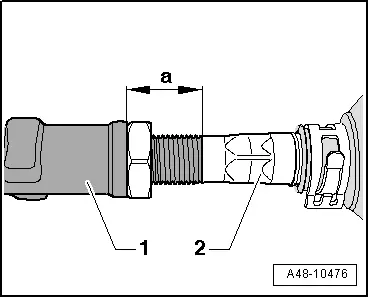
- Loosen lock nut -B-.
 Note
Note
Counterhold the tie rod end -C- when loosening the lock nut -B-.
- Adjust toe on left and right-hand wheels at hex -A-.
Be sure that boots are not twisted after turning tie rods!
Twisted boots wear out quickly.
- Tighten lock nut -B- and check toe-in value again. Refer to → Chapter "Steering Gear, Servicing, Hydraulic Power Steering Gear".
After tightening lock nut -B- it is possible that the value deviates slightly.
If the measured toe nevertheless lies within the tolerance, the adjustment is correct.