Audi Q5: Overview - Radio
Radio Components
The radio consists of:
Symphony radio
- Radio with integrated CD changer
- Display Mid
- Sound systems: basic/basic plus/Standard (8RX/9VD)
- SD Memory Card Reader
- Satellite Radio -R146- integrated in symphony sound system
Optional
- Sound System: Bang & Olufsen, 9VK
- External Audio Source Connection -R199-
- Cell Phone Preparation
- Bluetooth hands-free calling
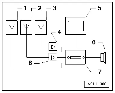
1 - Roof Antenna -R216- (Satellite Antenna -R170-)
2 - Antenna - R11- in Spoiler
3 - Radio Antenna 2 -R93- inside the Rear Window
4 - The Antenna Amplifier -R24- on bottom of rear lid
5 - Front Information Display Control Head -J685- in the instrument panel
6 - Sound Systems
7 - Radio -R- in the instrument panel
8 - Antenna Amplifier 3 -R112- on top of the rear lid
The connection to other vehicle systems takes place via the Infotainment CAN Bus and the Data Bus On Board Diagnostic Interface -J533-.
Perform the Fault Finding with the Vehicle Diagnostic Tester.
Component Location Overview - Radio
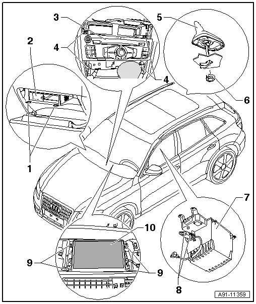
1 - Radio Removal Tool -T10057-
2 - External Audio Source Connection -R199- (AMI)
- Connector assignments AMI (CAN). Refer to → Chapter "External Audio Source Connection -R199- Connector Assignment, AMI, CAN".
- Removing and Installing, (AMI). Refer to → Chapter "External Audio Source Connection -R199-, Removing and Installing, AMI".
3 - Radio -R-
- Symphony Connector Assignment. Refer to → Chapter "Radio Connector Assignment, Symphony"
- Removing and installing. Refer to → Chapter "Radio -R-, Removing and Installing".
4 - Bolt
- 3 Nm
5 - Roof Antenna -R216-
- Antenna Systems. Refer to → Chapter "Antenna Systems".
6 - Nut
- 6 Nm
7 - Storage Compartment
8 - External Audio Source Connection -R199-, AUX IN
- AUX-IN connector assignment. Refer to → Chapter "External Audio Source Connection -R199-, Connector Assignment, AUX IN".
- AUX IN, Removing and Installing. Refer to → Chapter "External Audio Source Connection -R199-, Removing and Installing, AUX IN".
9 - Bolt
- 2 Nm
10 - Front Information Display Control Head -J685-
- Connector Assignment (CAN). Refer to → Chapter "Display Connector Assignment, CAN".
- Removing and installing. Refer to → Chapter "Infotainment System Display, Removing and Installing".

