Audi Q5: Radio Connector Assignment, Symphony
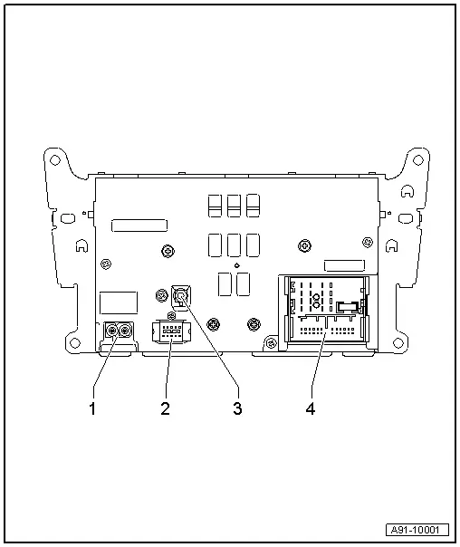
1 - (AM/FM1/FM2) antenna jack
2 - Black 10-pin connector (T10v) for the Front Information Display Control Head -J685-
3 - Black Antenna Connection (Satellite Tuner) from Roof Antenna -R216- (Satellite Antenna -R170-)
4 - Black connection block with four multipin connectors
 Note
Note
Unlisted connector terminals are not assigned.
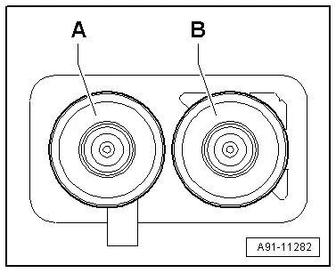
1 - AM/FM1/FM2 antenna connection
A - Chamber 2 (AM/FM1) from Antenna Amplifier 3 -R112- (Antenna -R11-)
B - Chamber 1 (FM2) from Antenna Amplifier -R24- (Radio Antenna 2 -R93-)
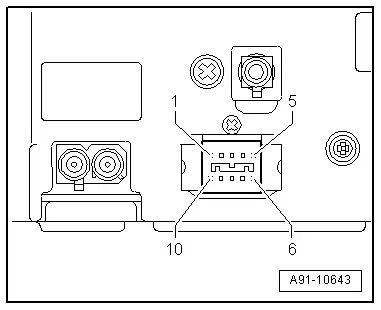
2 - Black 10-pin connector (T10v)
All pins are connected to the Front Information Display Control Head -J685-.
1 - Power Supply
2 - Ground
3 - Not Assigned
4 - Diag. Display
5 - Diag. Cable
6 - LVDS OUT (+)
7 - LVDS OUT (-)
8 - LVDS OUT ground
9 - Diag. T0
10 - Diag. T1
4 - Connection block with four multipin connectors
A - Brown 8-pin connector (T8k)
1 - Right rear speaker (+)
2 - Right front speaker (+)
3 - Left front speaker (+)
4 - Left rear speaker (+)
5 - Right rear speaker (-)
6 - Right front speaker (-)
7 - Left front speaker (-)
8 - Left rear speaker (-)
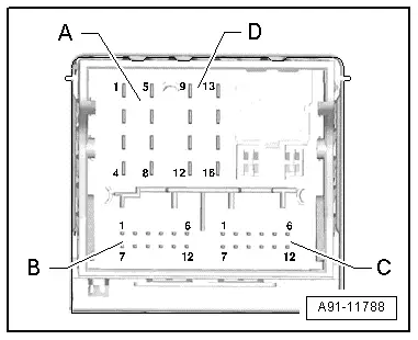
B - Blue 12-pin multipin connector (T12s)
1 - Left LF-In from the External Audio Source Connection -R199-
2 - LF-In ground from the External Audio Source Connection -R199-
3 - Ground
4 - Permanent positive
5 - Not Assigned
6 - DATA OUT
7 - Right LF-In from the External Audio Source Connection -R199-
8 - Left signal
9 - Right signal
10 - Positive switched
11 - DATA IN
12 - CLK

C - Green 12-pin connector (T12a)
1 - Microphone IN (-)
2 - Right LF OUT
3 - LF OUT ground
4 - Microphone OUT (-)
5 - Left LF IN (-)
6 - LF (-) from Telephone Transceiver -R36-
7 - Microphone IN (+)
8 - Left LF OUT
9 - Microphone OUT (+)
10 - LF mute
11 - Left LF IN (+)
12 - LF (+) from Telephone Transceiver -R36-

D - Black 8-pin connector (T16l)
9 - CAN Bus high (Infotainment)
10 - CAN Bus low (Infotainment)
12 - Terminal 31
15 - Terminal 30
16 - Permanent positive (not used)


