Audi Q5: Overview - Rear Bumper Cover
Overview - Bumper Cover, Audi Q5
 Caution
If the vehicle has lane change assistance, the lane change assistance control module -J769-/-J770- must be recalibrated. Refer to → Electrical Equipment; Rep. Gr.96; Lane Change Assistance; Lane Change Assistance, Calibrating.
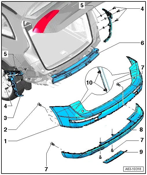
1 - Rear Bumper Cover
- Removing and installing. Refer to → Chapter "Bumper Cover, Removing and Installing".
2 - Bolt
- 1.5 Nm
3 - Guide Piece
- Removing and installing. Refer to → Chapter "Bumper Guide Pieces, Removing and Installing".
4 - Bolt
- 1.5 Nm
5 - Clip
6 - Impact Member
7 - Bolt
- 1.5 Nm
8 - Spoiler
- Equipment levels
- Removing and installing. Refer to → Chapter "Attachments, Removing and Installing".
9 - Trim
10 - Clips
- Unclip on both sides before removing the bumper cover to the rear.
- There are different numbers of clips. Refer to the Parts Catalog.
Overview - Bumper Cover, Audi Q5 S-Line and Audi SQ5
 Caution
If the vehicle has lane change assistance, the lane change assistance control module -J769-/-J770- must be recalibrated. Refer to → Electrical Equipment; Rep. Gr.96; Lane Change Assistance; Lane Change Assistance, Calibrating.
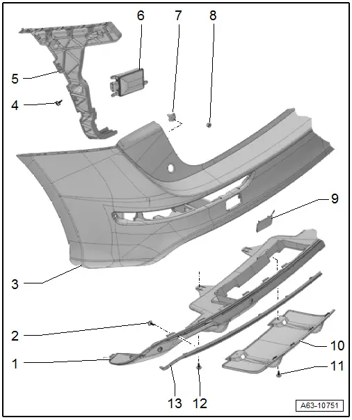
1 - Spoiler
- Different versions. Refer to the Parts Catalog.
- Removing and installing. Refer to → Chapter "Attachments, Removing and Installing".
2 - Bolt
- Quantity: 10
- 2.2 Nm
3 - Rear Bumper Cover
- Removing and installing. Refer to → Chapter "Bumper Cover, Removing and Installing".
4 - Bolt
- Tightening sequence, refer to -item 4-
5 - Guide Piece
- Removing and installing. Refer to → Chapter "Bumper Guide Pieces, Removing and Installing".
6 - Lane Change Assistance Control Module
- Equipment levels
- Overview. Refer to → Electrical Equipment; Rep. Gr.96; Lane Change Assistance; Overview - Lane Change Assistance.
7 - Clip
8 - Nut
- 4 Nm
- Quantity: 4
9 - Cover
- For the towing eye.
10 - Trim
11 - Bolt
- 1.5 Nm
- Quantity: 2
12 - Bolt
- 1.5 Nm
- Quantity: 2
13 - Trim Strip
- For the bumper cover spoiler
- Removing and installing. Refer to → Chapter "Attachments, Removing and Installing".

