Audi Q5: Overview - Wheel Bearing
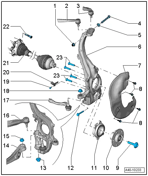
1 - Nut
- 40 Nm
- Always replace if removed
2 - Upper Front Control Arm
3 - Upper Rear Control Arm
4 - Bolt
- Always replace if removed
5 - Washer
6 - Wheel Bearing Housing
- Removing and installing. Refer to → Chapter "Wheel Bearing Housing, Removing and Installing".
- There are different versions. For allocation. Refer to the Parts Catalog.
- Distinguishing characteristic.
 WARNING
When exchanging the wheel bearing housing, make sure the length of the thread on the tie rod end is sufficient (there must be approximately 5 mm extra thread). If this is not the case, then install a new tie rod end with a longer thread pin. Refer to the Parts Catalog.
7 - Brake Shield
8 - Bolt
- 10 Nm
9 - Bolt
- 200 Nm +180º
- Replace after each removal. Refer to → Chapter "Driveshaft General Information".
- Before installing, clean the threads in the CV joint with a tap.
10 - Wheel Hub
- Removing and installing. Refer to → Chapter "Wheel Bearing Unit, Servicing".
11 - Wheel Bearing
- Removing and installing. Refer to → Chapter "Wheel Bearing Unit, Servicing".
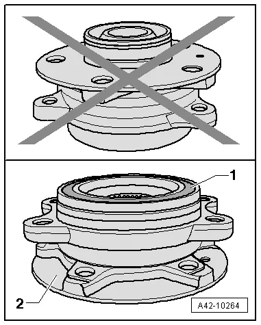
 Caution
Avoid contaminating with dirt and damaging the seal when setting down/storing. Refer to → Fig. "Avoid contaminating with dirt and damaging the seal when setting down/storing.".
12 - Bolt
- 40 Nm
- Always replace if removed
13 - Nut
- Always replace if removed
- There are different versions. For allocation. Refer to the Parts Catalog.
- There are different versions and tightening specifications.
- After loosening threaded connection of guide control arm to wheel bearing housing, adhesive residue must be removed on thread of linkage stub.
14 - Control Arm
15 - Nut
- Always replace if removed
- There are different versions. For allocation. Refer to the Parts Catalog.
- There are different versions and tightening specifications.
- After loosening threaded connection on the ball joint to the wheel bearing housing, adhesive residue must be removed on thread of linkage stub.
16 - Guide Link
17 - Tie Rod End
- There are different versions. For allocation. Refer to the Parts Catalog.
18 - Nut
- There are different versions. For allocation. Refer to the Parts Catalog.
- Pay attention to the different nut versions and to the tightening specifications.
- Always replace if removed
19 - Bolt
- 9 Nm
20 - Speed Sensor
21 - Drive Axle
22 - Bolt
- 70 Nm
- Always replace if removed
23 - Cap Screws
- 80 Nm +90º
- Always replace if removed
Avoid contaminating with dirt and damaging the seal when setting down/storing.
- The wheel bearing -1- must always face up.
- Always set the wheel bearing unit down on the wheel hub -2-.
Nut versions for the tie rod ball joint bracket
- Hex collar nut -A-
Tightening specification: 20 Nm 90º.
- Twelve-point combination nut -B-
Tightening specification: 100 Nm
- Hex combi nut -C-
Tightening specifications: 110 Nm
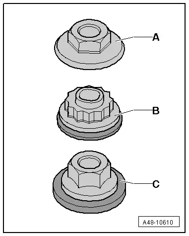
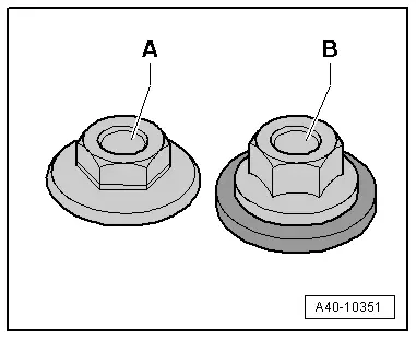
Nut versions for the control arm and guide link bracket
- Hex - collar nut -A- M12 wrench 21 mm
Tightening specification: 145 Nm
- Hex - combination nut -B- M12 18 mm
Tightening specifications: 110 Nm
- Hex - combination nut -B- M12 21 mm
Tightening specification: 120 Nm
- Hex - combination nut -B- M14 21 mm
Tightening specification: 140 Nm
Wheel bearing housing with different steering arm thickness
- The wheel bearing housing differs in the thickness of the steering arm -2-.