Audi Q5: Telephone Baseplate -R126-, Removing and Installing
Telephone Baseplate -R126-, Removing and Installing, Cradle
- Turn off the ignition and all electrical consumers and remove the ignition key.
 WARNING
Danger of unintended engine ignition
Turn off the ignition and remove the ignition key from the vehicle interior for all work performed on the high voltage vehicle.
Removing
- Remove the Telephone Handset -R37-.
- Remove SIM card mount.
- Remove the center console storage compartment. Refer to → Body Interior; Rep. Gr.68; Center Console; Front Center Console Storage Compartment, Removing and Installing.
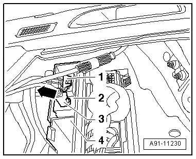
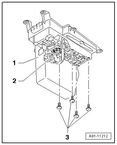
- Disconnect the connector from the Telephone Baseplate -R126--2-.
- Remove the screws -3- on the back of the storage compartment -1-.
- Push Telephone Baseplate -R126--2- upward out of storage compartment -1-.
Installing
- Install in reverse order of removal.
Tightening specifications and installation instructions can be found in the Component Location Overview. Refer to → Chapter "Component Location Overview - Telephone System".
Telephone Baseplate -R126-, Removing and Installing, Cell Phone Mount
- Turn off the ignition and all electrical consumers and remove the ignition key.
 WARNING
Danger of unintended engine ignition
Turn off the ignition and remove the ignition key from the vehicle interior for all work performed on the high voltage vehicle.
Removing
- Remove the center console storage compartment. Refer to → Body Interior; Rep. Gr.68; Center Console; Front Center Console Storage Compartment, Removing and Installing.
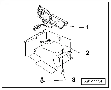
- Disconnect the connector from the Telephone Baseplate -R126--1-.
- Remove the bolts -3- on the back side.
- Push the Telephone Baseplate -R126--1- upward out of storage compartment -2-.
Installing
- Install in reverse order of removal.
Tightening specifications and installation instructions can be found in the Component Location Overview. Refer to → Chapter "Component Location Overview - Telephone System".
Telephone Transceiver, Removing and Installing
The Telephone Transceiver -R36- is located under the right front seat.
- If replacing the control module, select the "Replace Control Module" function on the Vehicle Diagnostic Tester.
Use Vehicle Diagnostic Tester.
- Turn off the ignition and all electrical consumers and remove the ignition key.
 WARNING
Danger of unintended engine ignition
Turn off the ignition and remove the ignition key from the vehicle interior for all work performed on the high voltage vehicle.
Removing
- Remove the right front seat. Refer to → Body Interior; Rep. Gr.72; Front Seats; Front Seat, Removing and Installing.
- Fold back the floor covering. Refer to → Body Interior; Rep. Gr.70; Passenger Compartment Trim; Carpet, Removing and Installing.
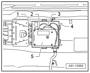
- Disengage cover of E-box -2- and open the E-box -1-.
The Telephone Transceiver -R36- is only wedged into the electronics box.
- Pry the Telephone Transceiver -R36--5- out of the E-box -4-.
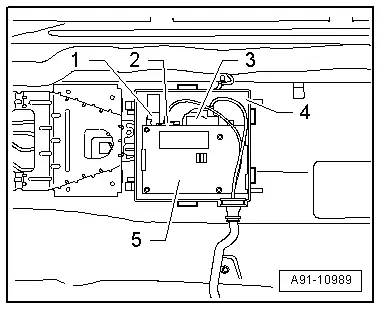
- Disconnect the connector -3- (connector -2- not installed).
- Disconnect the Bluetooth Antenna -R152--1-.
Installing
- Install in reverse order of removal.
- Readapt the Bluetooth connection between the Telephone Transceiver -R36- and Cellular Telephone -R54-.
Tightening specifications and installation instructions can be found in the Component Location Overview. Refer to → Chapter "Component Location Overview - Telephone System".
Parking Heater Radio Receiver -R64-, Removing and Installing
The Parking Heater Radio Receiver -R64- is located behind the right luggage compartment side trim panel above the Cellular Telephone Amplifier -R86-.
The Parking Heater Radio Receiver -R64- is attached to the Parking Heater Radio Receiver -R64-/Cellular Telephone Amplifier -R86- bracket.
- Turn off the ignition and all electrical consumers and remove the ignition key.
 WARNING
Danger of unintended engine ignition
Turn off the ignition and remove the ignition key from the vehicle interior for all work performed on the high voltage vehicle.
Removing
- Remove the cover from the right luggage compartment side trim panel.
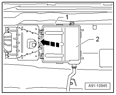
- Disconnect the connectors -1- and -3- on the Parking Heater Radio Receiver -R64--2-.
- Push the tab -arrow- outward and remove the Parking Heater Radio Receiver -R64--2- from the bracket -4-.
Installing
- Install in reverse order of removal.
Tightening specifications and installation instructions can be found in the Component Location Overview. Refer to → Chapter "Component Location Overview - Telephone System".