Audi Q5: Driver Side Airbag
Overview - Driver Side Airbag
Driver Side Airbag, Assembly Overview, Bolted Airbag Version
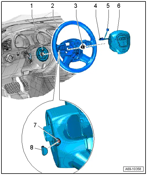
1 - Steering Column Electronics Control Module -J527-
- With Airbag Spiral Spring/Return Spring with Slip Ring -F138- and Steering Angle Sensor -G85-
- Overview. Refer to → Electrical Equipment; Rep. Gr.94; Steering Column Switch Module; Overview - Steering Column Switch Module.
2 - Steering Wheel
- Equipment levels
- Overview. Refer to → Suspension, Wheels, Steering; Rep. Gr.48; Steering Wheel; Overview - Steering Wheel.
3 - Bolt
- Tightening specification. Refer to → Suspension, Wheels, Steering; Rep. Gr.48; Steering Wheel; Overview - Steering Wheel.
4 - Connector
- For the Driver Airbag Igniter -N95- and Driver Airbag Igniter 2 -N250-
- Replacing. Refer to → Chapter "Airbag Connector, Replacing".
5 - Connector
- For vehicles equipped with a multi-function steering wheel
- Replacing. Refer to → Chapter "Airbag Connector, Replacing".
6 - Driver Side Airbag
- With Driver Airbag Igniter -N95- and Driver Airbag Igniter 2 -N250-
 WARNING
Follow all Safety Precautions when working with pyrotechnic components. Refer to → Chapter "Pyrotechnic Components Safety Precautions".
- Removing and installing. Refer to → Chapter "Airbag Unit with Igniter, Removing and Installing, Bolted Airbag Version".
7 - Bolt
- 7 Nm
- Quantity: 2
8 - Cover Cap
- Quantity: 2
- For driver side airbag bolt
Driver Side Airbag, Assembly Overview, Attached Airbag Version
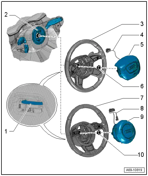
1 - Locking Bracket
- Use a T25 TORX screwdriver, approximately 100 mm long
2 - Steering Column Electronics Control Module -J527-
- With Airbag Spiral Spring/Return Spring with Slip Ring -F138- and Steering Angle Sensor -G85-
- Overview. Refer to → Electrical Equipment; Rep. Gr.94; Steering Column Switch Module; Overview - Steering Column Switch Module.
3 - 4-Spoke Steering Wheel
- Equipment levels
- Overview. Refer to → Suspension, Wheels, Steering; Rep. Gr.48; Steering Wheel; Overview - Steering Wheel.
4 - Wiring Harness
- For the Driver Airbag Igniter -N95- and Driver Airbag Igniter 2 -N250-
- Replacing. Refer to → Chapter "Airbag Connector, Replacing".
- Press in to secure in the pockets on the steering wheel.
5 - Driver Side Airbag
- With Driver Airbag Igniter -N95- and Driver Airbag Igniter 2 -N250-
 WARNING
Follow all Safety Precautions when working with pyrotechnic components. Refer to → Chapter "Pyrotechnic Components Safety Precautions".
- Removing and installing. Refer to → Chapter "Airbag Unit with Igniter, Removing and Installing, Attached Airbag Version".
6 - Bolt
- Tightening specification. Refer to → Suspension, Wheels, Steering; Rep. Gr.48; Steering Wheel; Overview - Steering Wheel.
7 - 3-Spoke-Steering Wheel
- Equipment levels
- Overview. Refer to → Suspension, Wheels, Steering; Rep. Gr.48; Steering Wheel; Overview - Steering Wheel.
8 - Wiring Harness
- For the Driver Airbag Igniter -N95- and Driver Airbag Igniter 2 -N250-
- Replacing. Refer to → Chapter "Airbag Connector, Replacing".
- Press in to secure in the pockets on the steering wheel.
9 - Driver Side Airbag
- With Driver Airbag Igniter -N95- and Driver Airbag Igniter 2 -N250-
 WARNING
Follow all Safety Precautions when working with pyrotechnic components. Refer to → Chapter "Pyrotechnic Components Safety Precautions".
- Removing and installing. Refer to → Chapter "Airbag Unit with Igniter, Removing and Installing, Attached Airbag Version".
10 - Bolt
- Tightening specification. Refer to → Suspension, Wheels, Steering; Rep. Gr.48; Steering Wheel; Overview - Steering Wheel.

