Audi Q5: Final Drive Removing and Installing 0BC, Audi A4, A5, A6, A7, and Q% (not Q5 Hybrid)
Special tools and workshop equipment required
- Engine and Gearbox Jack -VAS6931- with Universal Transmission Support -VAG1359/2-
- Tensioning Strap -T10038-
- Engine/Gearbox Jack Adapter - Wheel Hub Support - T10149-
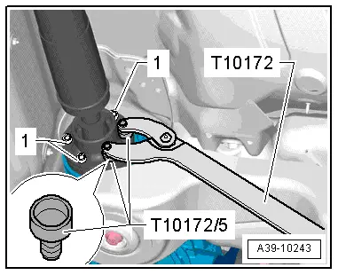
- Counterhold - Kit - Multiple Use -T10172- with Counterhold - Kit - Adapter 5 - T10172/5-
- Socket - Xzn 12 -T40154-
Removal
Pay attention to the general repair information. Refer to → Chapter "Repair Information".
- Place the vehicle on a lift.
- Remove the wheel hubcap from the left rear wheel. On alloy wheels, remove the cap using the puller in the vehicle tool kit.
- Remove the left rear wheel.
Vehicles with 6- or 8-Cylinder Engines (except for Q5)
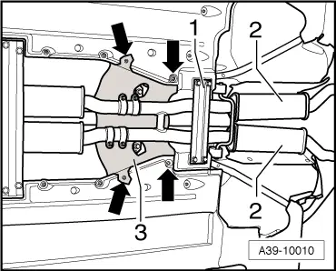
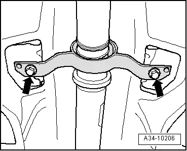
- Remove the rear crossmember -1-.
- Remove the rear section of the exhaust system -2-. Refer to → Rep. Gr.26; Exhaust Pipes/Mufflers; Overview - Muffler.
 Note
Note
A second technician is needed to help remove the rear section of the exhaust system.
- Secure the rear crossmember -1- again to the body.
Continuation for all Vehicles
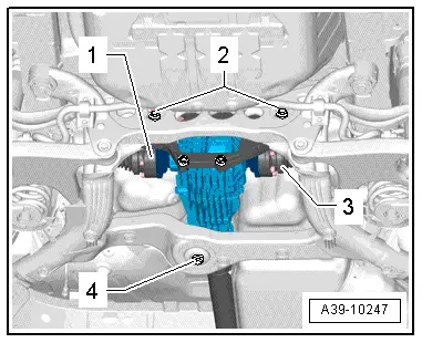
- Remove the heat shield -3--arrows-.

- Remove the driveshaft from the rear final drive. Refer to → Chapter "Drive Shaft, Removing and Installing from Rear Final Drive".
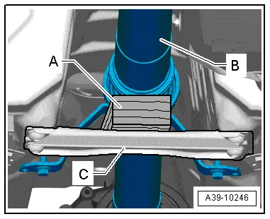
- Place a block of wood -A- (approximately 40 mm high) on the rear crossmember -C- and support the driveshaft -B-.
 Note
Note
- The driveshaft -B- is supported under the intermediate bearing by the heat shield on the Audi Q5.
- The driveshaft can be bent all the way to the center joint without force. Bending the joint forcibly all the way can damage the center joint and/or the protective boot.
- Remove the driveshaft intermediate bearing mounting bolts -arrows-.
- Push the driveshaft forward and at the same time remove it from the rear final drive.
- Secure the driveshaft on the side to the subframe.

- Remove the left drive axle heat shield -A- from the crossmember/rear final drive -arrows-.
- Remove the left -1- and right -3- drive axles.
- Loosen the bolts -2- approximately three turns.
- Remove the bolt -4-.
- Position the Engine and Gearbox Jack -VAS6931- and the Universal Transmission Support -VAG1359/2- and a block of wood -A- (approximately 80 mm tall) under the rear final drive.
 Note
Note
Pay attention that the Universal Transmission Support -VAG1359/2- does not make contact with the fuel tank.
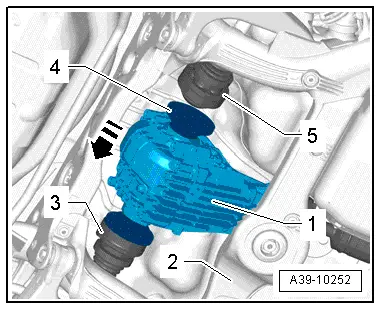
- Remove the bolts -1- (lower bolts attaching the crossmember to the rear final drive) and -2-.
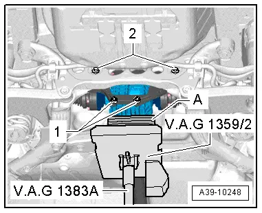
- Remove the two upper bolts that connect the crossmember -B- to the rear final drive.
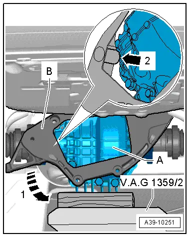
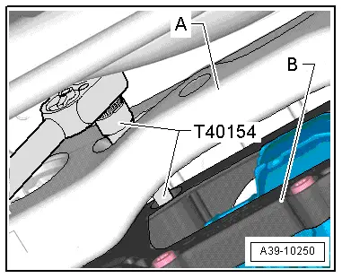
- Guide the Socket - Xzn 12 -T40154- through the holes in the subframe -A-. Move the final drive to the left or right just a little, if necessary.

- Move the final drive -A- forward slightly.
- Turn the lower crossmember -B- direction of -arrow 1- and guide the final drive -arrow 2- and remove it.
 Note
Note
- A second technician must help with the next steps.
- Before raising the left rear suspension, secure the vehicle to the lifting arm on the hose using a Tensioning Strap -T10038-.
- Remove the Engine and Gearbox Jack -VAS6931- from under the final drive while a second technician keeps the rear final driving from falling down.
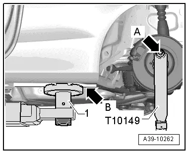
- Insert the Engine/Gearbox Jack Adapter - Wheel Hub Support - T10149- in the Engine and Gearbox Jack -VAS6931-.
- Attach the Engine/Gearbox Jack Adapter - Wheel Hub Support -T10149- using a wheel bolt -arrow A- to the left rear suspension wheel hub.
- Lift the left rear suspension using the Engine and Gearbox Jack -VAS6931- just until the support arm -1- on the vehicle hoist just starts to lift the vehicle -arrow B-.
 WARNING
- Do not raise or lower the vehicle when the Engine and Gearbox Jack -VAS6931- is underneath it.
- Do not leave the Engine and Gearbox Jack -VAS9631- under the vehicle longer than necessary.
- The second technician must now push the rear final drive -1- toward the left side of the vehicle in direction of -arrow-.
- Then guide the right drive axle -5- upward out of the final drive flange shaft -4-.
- Guide the left drive axle -3- out and then, together with the second technician, remove the final drive from the subframe -2- toward the rear.
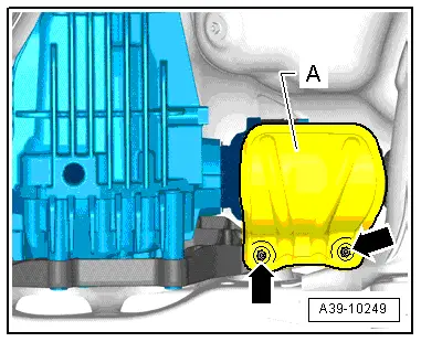
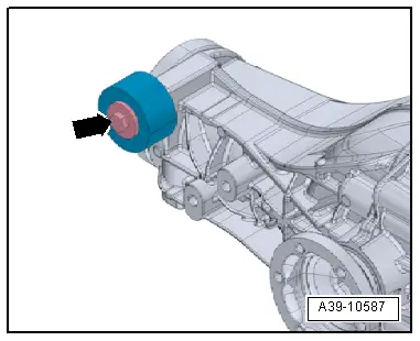
- If the rear final drive is replaced, the balance weight -arrow- must be rebuilt on the new rear final drive.
Installing
Install in reverse order of removal.
- With a second technician, position the rear final drive -1- on the subframe -2- in its installed position.
- Insert the left drive axle -3- into the final drive flange shaft.
- The second technician must now push the rear final drive -1- toward the left side of the vehicle in direction of -arrow-.
- Then install the right drive axle -5- into the final drive flange shaft -4-.
- Remove the Engine and Gearbox Jack -VAS6931- with the Engine/Gearbox Jack Adapter - Wheel Hub Support -T10149- from the left rear suspension.

- Position the Engine and Gearbox Jack -VAS6931- and the Universal Transmission Support -VAG1359/2- and a block of wood (approximately 80 mm tall) under the rear final drive -A-.
- Move the final drive -A- forward slightly.
- Turn the upper crossmember -B- opposite the direction of -arrow 1- to the left and insert it while guiding it past the final drive -arrow 2-.

- Tighten the four bolts connecting the crossmember -B- to the rear final drive diagonally. Tightening specification. Refer to -item 4-.
- Guide the Socket - Xzn 12 -T40154- through the holes in the subframe -A-. Move the final drive to the left or right just a little, if necessary.
- First tighten the bolt -2 and 4- hand-tight.
 Note
Note
For better illustration the Engine and Gearbox Jack -VAS6931- with the Universal Transmission Support -VAG1359/2- are not shown.
- Tighten the bolt -4-. Tightening specification. Refer to -item 3-.
- Tighten the bolts -2-. Tightening specification. Refer to -item 2-.
- Remove the Engine and Gearbox Jack -VAS6931- from under the final drive.
- Tighten the left -1- and right -3- drive axles. Refer to → Suspension, Wheels, Steering; Rep. Gr.42; Drive Axle; Drive Axle, Removing and Installing.

- Attach the left drive axle heat shield -A- to the crossmember/rear final drive -arrows--item 6-.

- Attach the driveshaft to the rear final drive.
- Attach the driveshaft intermediate bearing to the body free of tension. Tightening specification. Refer to -item 8-.
- Check the gear oil level in the rear final drive. Refer to → Chapter "Gear Oil, Checking Level, 0BC".
- Attach the heat shield -3- to the body -arrows-.
- Install the rear section of the exhaust system and align it so it is free of tension. Refer to → Rep. Gr.26; Exhaust Pipes/Mufflers; Overview - Muffler.
- If equipped, install the cross member -1-. Refer to → Body Exterior; Rep. Gr.66; Underbody Panel; Overview - Underbody Panels.
- Install the left rear wheel and tighten. Refer to → Suspension, Wheels, Steering; Rep. Gr.44; Wheels and Tires.