Audi Q5 Owners & Service Manuals

Audi Q5: Name Badges and Emblems

Dimensions - Rear Lid Name Badges and Emblems

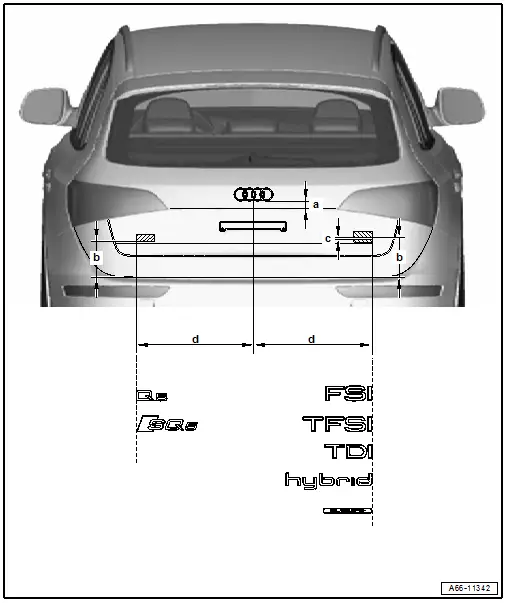
- Press the emblems firmly onto the body according to the dimensions.
Audi Q5. Dimensions - Rear Lid Name Badges and Emblems

  • Dimension -a- = 18 mm
  • Dimension -b- = 176 mm
  • Dimension -c- = 4 mm
  • Dimension -d- = 540 mm

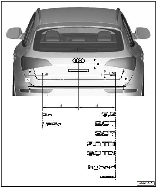
  Audi Q5. Dimensions - Rear Lid Name Badges and Emblems

  • Dimension -a- = 18 mm
  • Dimension -b- = 176 mm
  • Dimension -c- = 4 mm
  • Dimension -d- = 540 mm

Market-Specific Variants
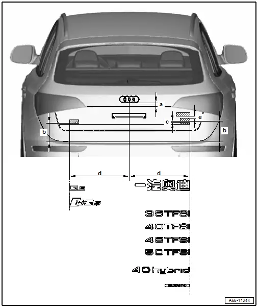
Audi Q5. Market-Specific Variants

  • Dimension -a- = 18 mm
  • Dimension -b- = 176 mm
  • Dimension -c- = 4 mm
  • Dimension -d- = 540 mm

  Note

Dimension -e- applies only to the emblem for China.

Dimension -e- = 15 mm

Dimensions - Name Badges and Emblems on Fender

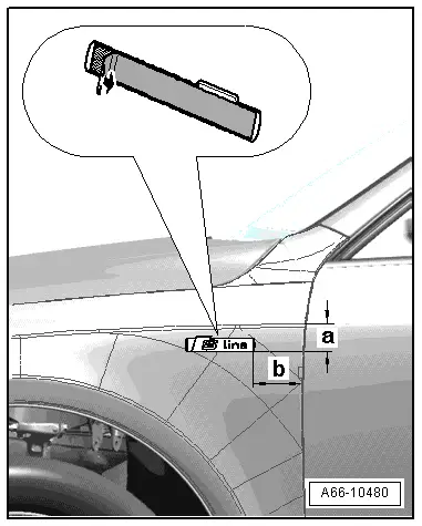
- Press the name badges firmly onto the body according to the dimensions.

Additional lettering, refer to → Fig. "S-Line Name Badge"
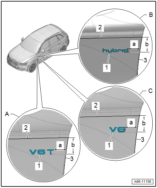
Audi Q5. Dimensions - Name Badges and Emblems on Fender

A - V6T Name Badge

  • Dimension -a- = 55 mm
  • Dimension -b- = 47 mm

-1-"V6T" emblem

-2- Cover edge in fender

-3- Cover edge in fender

B - Hybrid Name Badge

  • Dimension -a- = 55 mm
  • Dimension -b- = 47 mm

-1-"hybrid" emblem

-2- Cover edge in fender

-3- Cover edge in fender

C - V6 Name Badge

  • Dimension -a- = 55 mm
  • Dimension -b- = 47 mm

-1-"V6" emblem

-2- Cover edge in fender

-3- Cover edge in fender

S-Line Name Badge

  • Dimension -a- = 85 mm
  • Dimension -b- = 35 mm.

Audi Q5. A66-10480

    READ NEXT:

     Front Emblem, Removing and Installing

    Front Emblems, Removing and Installing, Brand Emblems Removing - Remove the reinforcement brace, refer to → Chapter "Reinforcement Brace, Removing and Installing". - Lift the tab -4-

     Trailer Hitch

    Overview - Hand Actuator Bracket 1 - Bracket for the Trailer Hitch Hand Actuator Removing and installing. Refer to → Chapter "Hand Actuator Bracket, Removing and Installing". 2&n

     Body  Interior

    SEE MORE:

     Folding chocks

    The folding chocks are part of the onboard tool kit. Fig. 210 Opening folding chocks To use the chocks, you first have to raise the support plate > fig. 210 1 and then insert the locking plate with the two "tabs" into the elongated holes in the base plate 2. WARNING The chock cannot fulfill it

     Drip Rail, Removing and Installing

    1 - Blind Rivet Quantity: 5 Rivet the guide rails beginning at the top. 2 - Guide Rail To remove, drill out rivet heads -4- and drive out rivet shafts. 3 - Drip Rail Press into the guide rail as far as the stop, beginning at the top and working toward the bo

    © 2019-2026 Copyright www.audiq5.net