Audi Q5: Overview - Lower Control Arm and Ball Joint
Audi Q5 Type 8R (2008 - 2017) Service Manual / Chassis / Suspension, Wheels, Steering / Front Suspension / Overview - Lower Control Arm and Ball Joint
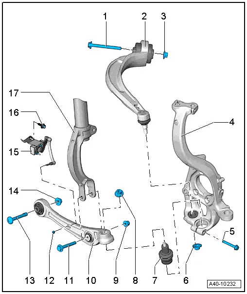
1 - Bolt
- Always replace if removed
2 - Guide Link
- Removing and installing. Refer to → Chapter "Guide Link, Removing and Installing".
- There are conventional and hydraulic bonded rubber bushings. For the correct allocation. Refer to the Parts Catalog
- Conventional Bonded Rubber Bushing for Guide Link, Replacing, 65 mm diameter. Refer to → Chapter "Guide Link Bonded Rubber Bushing, Removing and Installing, Standard Bonded Rubber Bushing 65 mm Diameter".
- Replacing the hydraulic bonded rubber bushing 75 mm for the guide link. Refer to → Chapter "Guide Link Bonded Rubber Bushing, Removing and Installing, Hydraulic Bonded Rubber Bushing 75 mm Diameter"
3 - Nut
- 70 Nm +180º
- Always replace if removed
- Must be tightened in the curb weight position. Refer to → Chapter "Wheel Bearing in Curb Weight, Lifting Vehicles with Coil Spring".
4 - Wheel Bearing Housing
5 - Bolt
- 40 Nm
- Always replace if removed
6 - Nut
- Always replace if removed
- There are different versions. For allocation. Refer to the Parts Catalog.
- There are different versions and tightening specifications.
- After loosening threaded connection of guide control arm to wheel bearing housing, adhesive residue must be removed on thread of linkage stub.
7 - Ball Joint
- Removing and installing. Refer to → Chapter "Ball Joint, Removing and Installing".
- There are different versions. For allocation. Refer to the Parts Catalog.
 Note
Note
- Note the installation position.
- Install the ball joint into the wheel bearing housing as far as the contact surface.
8 - Nut
- There are different versions. For allocation. Refer to the Parts Catalog.
- There are different versions and tightening specifications.
- Always replace if removed
- After loosening threaded connection on the ball joint to the wheel bearing housing, adhesive residue must be removed on thread of linkage stub.
9 - Nut
- 90 Nm +90º
- Always replace if removed
- Must be tightened in the curb weight position. Refer to → Chapter "Wheel Bearing in Curb Weight, Lifting Vehicles with Coil Spring".
10 - Control Arm
- Removing and installing. Refer to → Chapter "Control Arm, Removing and Installing".
- There are different versions. For allocation. Refer to the Parts Catalog.
- Replacing bearings for track control arm. Refer to → Chapter "Control Arm Ball Bearing, Replacing"
11 - Bolt
- Always replace if removed
12 - Nut
- 9 Nm
13 - Bolt
- Always replace if removed
14 - Nut
- 70 Nm +180º
- Always replace if removed
- Must be tightened in the curb weight position. Refer to → Chapter "Wheel Bearing in Curb Weight, Lifting Vehicles with Coil Spring".
15 - Left/Right Front Level Control System Sensor -G78-/-G79-
- Only sensors of the same version may be installed.
- Only remove and install or replace completely. Refer to → Chapter "Left/Right Front Level Control System Sensor -G78-/-G289-, Removing and Installing".
- The sensor lever must point toward the back
- The headlamp basic setting must be checked after loosening. Refer to → Electrical Equipment; Rep. Gr.94; Headlamps; Headlamp, Adjusting.
- If the level control system sensor was removed and installed on a vehicle with electronically controlled damping or if the linkage was loosened, the control position must be reprogrammed using the Vehicle Diagnostic Tester. Refer to → Chapter "Control Position, Programming".
- If the control position was reprogrammed on vehicles with lane assist, the Directional Stabilization Assistance Control Module -J759- must be calibrated again. Refer to → Chapter "Lane Assist, Calibrating".
16 - Bolt
- 20 Nm
17 - Shock Absorber Fork
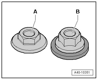
Nut versions for the control arm and guide link bracket
- Hex - collar nut -A- M12 wrench 21 mm
Tightening specification: 145 Nm
- Hex - combination nut -B- M12 18 mm
Tightening specifications: 110 Nm
- Hex - combination nut -B- M12 21 mm
Tightening specification: 120 Nm
- Hex - combination nut -B- M14 21 mm
Tightening specification: 140 Nm