Audi Q5: Special Tools
Audi Q5 Type 8R (2008 - 2017) Service Manual / Chassis / Suspension, Wheels, Steering / Rear Suspension / Special Tools
Special tools and workshop equipment required
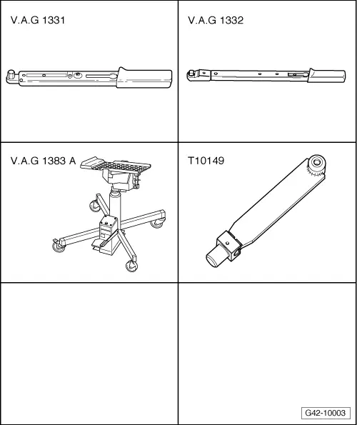
- Torque Wrench 1331 5-50Nm -VAG1331-
- Torque Wrench 1332 40-200Nm -VAG1332-
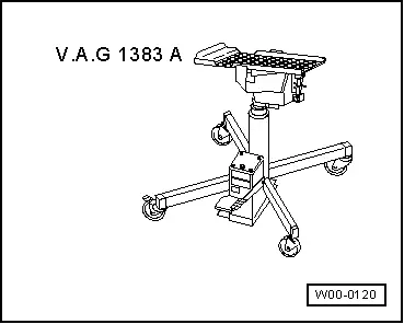
- Engine and Gearbox Jack -VAS6931-
- Engine/Gearbox Jack Adapter - Wheel Hub Support -T10149-
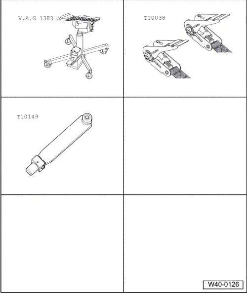
- Engine and Gearbox Jack -VAS6931-
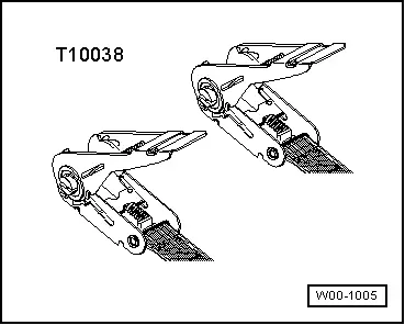
- Tensioning Strap -T10038-
- Engine/Gearbox Jack Adapter - Wheel Hub Support -T10149-
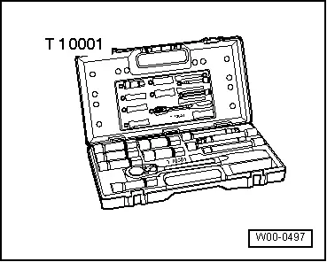
- Shock Absorber Set -T10001-
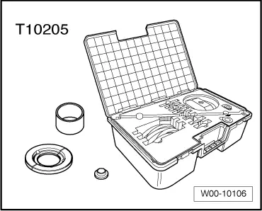
- Bearing Installer - Wheel Hub/Bearing Kit -T10205-
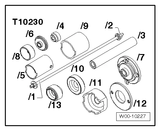
- Hydraulic Press - Bushing Assembly Tool Kit -T10230-
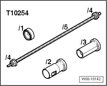
- Hydraulic Press - Ball Joint Assembly Tools -T10254-
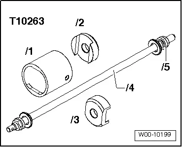
- Hydraulic Press - Rear Subframe Bushing Tool Kit -T10263-
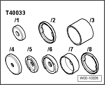
- Rear Bushing Tool -T40033-
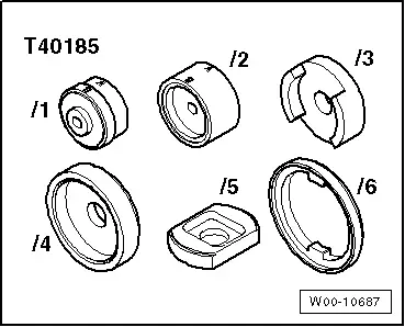
- Subframe Bushing Assembly Tool -T40185-
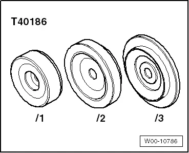
- Press Piece - Front Final Drive Bushing -T40186-
- Tensioning Strap -T10038-
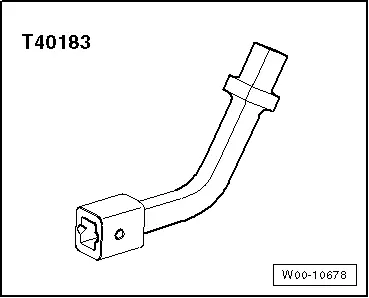
- Track Rod Tool Insert -T40183-
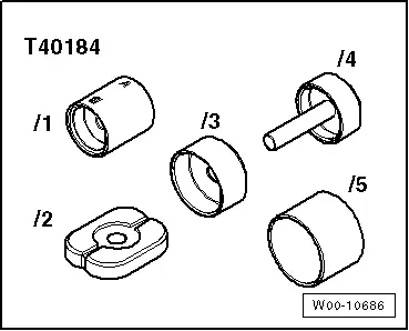
- Bearing Installer - Wheel Bearing Bushing -T40184-
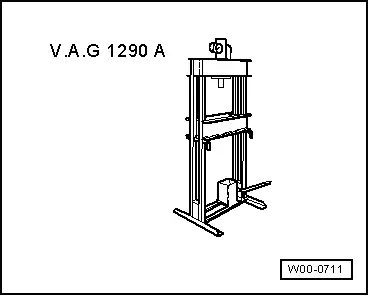
- Shop Press -VAG1290A-
- Universal Support Plate -VAG1359/2-
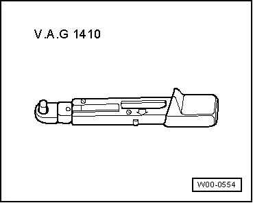
- Torque Wrench 1410 -VAG1410-
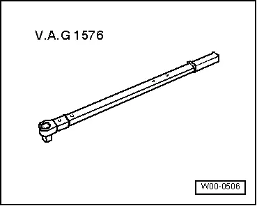
- Torque Wrench 80-400Nm -VAG1576-
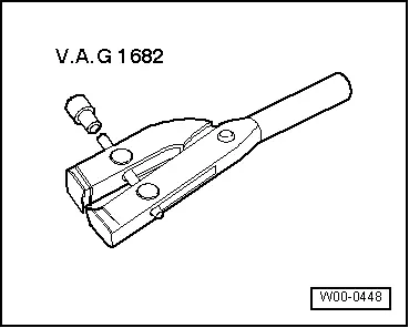
- Clamping Pliers -VAG1682A-
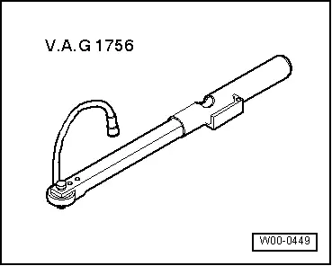
- Digital Torque Wrench -VAG1756A-
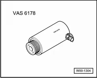
- Hydraulic Press -VAS6178-
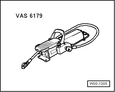
- Pneumatic/Hydraulic Foot Pump -VAS6179-
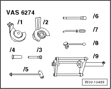
- Spring Tensioning System -VAS6274-
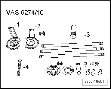
- Spring Tensioning System - Audi Set -VAS6274/10-
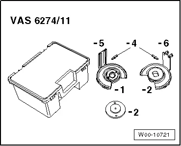
- Spring Tensioning System - Q5 Set -VAS6274/11-
- Engine and Gearbox Jack -VAS6931-
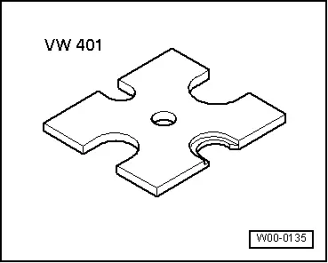
- Press Plate -VW401-
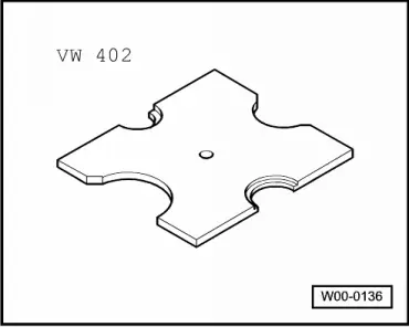
- Press Plate -VW402-
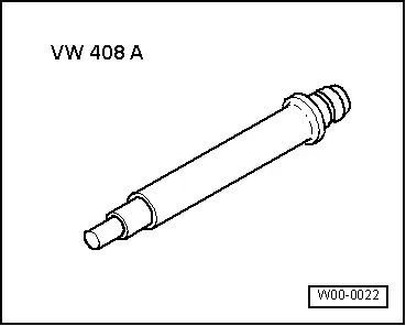
- Press Piece - Rod -VW408A-
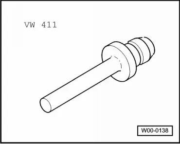
- Press Piece - Rod -VW411-
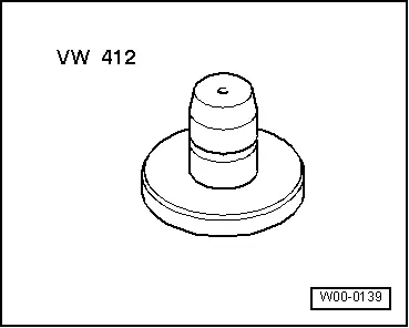
- Press Piece - Multiple Use -VW412-
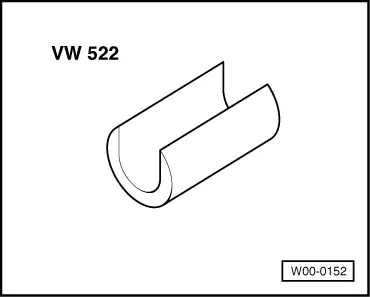
- CV Joint Press Sleeve -VW522-
- Puller - Kukko Separating Tool - Diameter 25-155mm -15/3-
- Puller - Kukko Quick Action Separating Tool - 25-155mm -17/3-
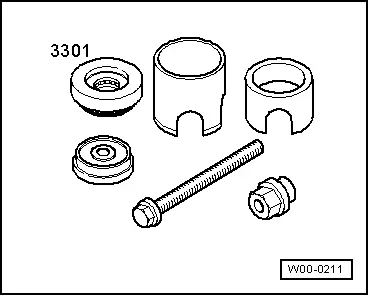
- Subframe Bushing Tool Kit -3301-
- Pliers -3340-
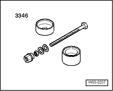
- Bearing Installer - Control Arm -3346-