Audi Q5: Overview - Instrument Panel Central Tube
Audi Q5 Type 8R (2008 - 2017) Service Manual / Body / Body Interior / Interior Trim / Overview - Instrument Panel Central Tube
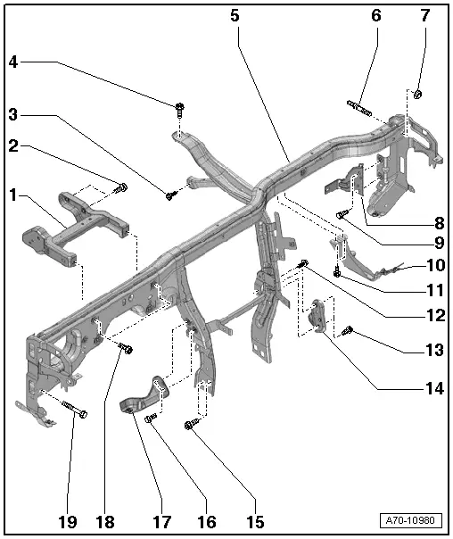
1 - Bracket
- Removing and installing. Refer to → Chapter "Mounting Bracket, Removing and Installing".
2 - Bolt
- 20 Nm
- Quantity: 4
3 - Bolt
- 3.6 Nm
4 - Bolt
- 20 Nm
5 - Central tube
- For the instrument panel
- Removing and installing. Refer to → Chapter "Instrument Panel Central Tube, Removing and Installing".
6 - Threaded Pin
- 20 Nm
- Quantity: 2
7 - Nut
- 20 Nm
- Quantity: 2
- Always replace if removed
8 - Bracket
- for the air intake chamber
9 - Bolt
- 9 Nm
- Quantity: 2
10 - Bracket
- For the glove compartment
- Removing and installing. Refer to → Chapter "Glove Compartment Mount, Removing and Installing".
11 - Bolt
- 9 Nm
- Quantity: 2
12 - Bolt
- 3.6 Nm
- Quantity: 2
13 - Bolt
- 9 Nm
- Quantity: 2
14 - Bracket
- For the glove compartment
15 - Bolt
- 20 Nm
- Quantity: 4
16 - Bolt
- 9 Nm
- Quantity: 2
17 - Bracket
- For the instrument panel cover
18 - Bolt
- 20 Nm
- Quantity: 2
19 - Bolt
- 20 Nm
Bumper and Glove Compartment Mount Assembly Overview
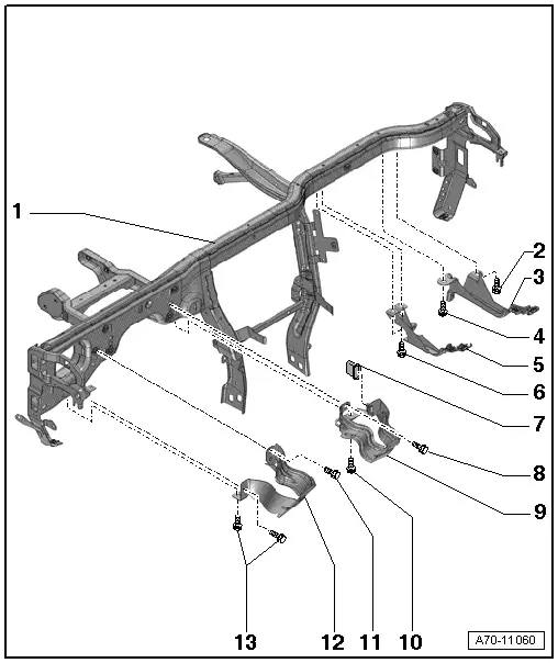
1 - Central Tube
2 - Bolt
- 9 Nm
3 - Right Retainer
- For the glove compartment
- Market-specific
- Removing and installing. Refer to → Chapter "Glove Compartment Mount, Removing and Installing".
4 - Bolt
- 9 Nm
5 - Left Retainer
- For the glove compartment
- Equipment level
- Removing and installing. Refer to → Chapter "Glove Compartment Mount, Removing and Installing".
6 - Bolt
- 9 Nm
- Quantity: 2
7 - Grommet
- Mounted on the impact absorber, refer to -item 9-
8 - Bolt
- Tightening Specification. Refer to → Rep. Gr.48; Steering Column; Overview - Steering Column.
9 - Right Shock Absorber
- Market-specific
- Removing and installing. Refer to → Chapter "Bumper, Removing and Installing".
10 - Bolt
- 9 Nm
11 - Bolt
- 9 Nm
12 - Left Shock Absorber
- Market-specific
- Removing and installing. Refer to → Chapter "Bumper, Removing and Installing".
13 - Bolt
- 9 Nm
- Quantity: 2

