Audi Q5: Sunroof Panel, Adjusting
Audi Q5 Type 8R (2008 - 2017) Service Manual / Body / Body Exterior / Sunroof / Sunroof Panel, Adjusting
 Note
Note
- Adjust the front glass sunroof panel only on the front edge and the rear glass sunroof panel on the rear edge.
- To achieve the best possible exterior optical characteristics, make sure that the adjustment on left and right sides is performed as evenly (symmetrically) as possible.
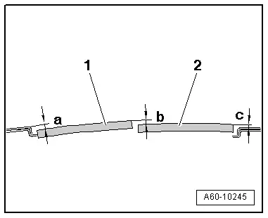
Height Adjustment, Checking
- Check the adjustment of the front -1- and rear -2- glass panels with a depth gauge.
- Dimension -a- : 1.5 +- 1 mm
- Dimension -b- : 1 +- 1 mm
- Dimension -c- : 1 +- 1 mm
- Front Glass Sunroof Panel, Adjusting.
- Adjust the rear glass panel.
Front Glass Sunroof Panel, Adjusting
- Remove the trim. Refer to → Chapter "Sunroof Panel, Removing and Installing".

- Remove both left and right front screws -arrows- on the glass panel -1-.
- Close the glass panel.
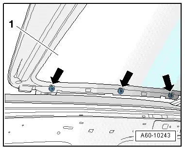
- Adjust the glass panel -1- according to the illustration.
- Dimension -a- : 1.5 +- 1 mm
- Dimension -b- : 1 +- 1 mm
- Dimension -c- : 1 +- 1 mm
- Tighten the left and right screws to 4.5 Nm.
- Install the trim.
Rear Glass Sunroof Panel, Adjusting
- Gently pull the inner seal -3- toward the inside on the marked locations -arrow- and loosen the screws -2- for the rear glass panel -1-.
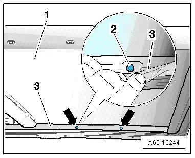
- Adjust the rear glass panel -2- according to the illustration.
- Dimension -a- : 1.5 +- 1 mm
- Dimension -b- : 1 +- 1 mm
- Dimension -c- : 1 +- 1 mm
- Tighten the screws to 4.5 Nm.


